BridgeBar®
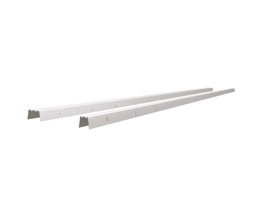
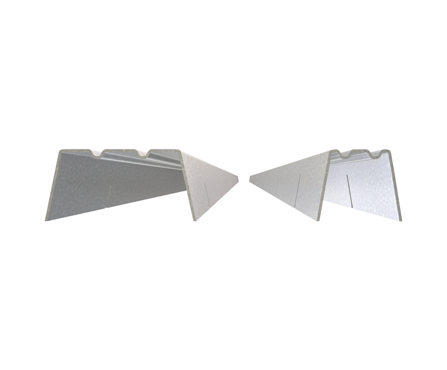
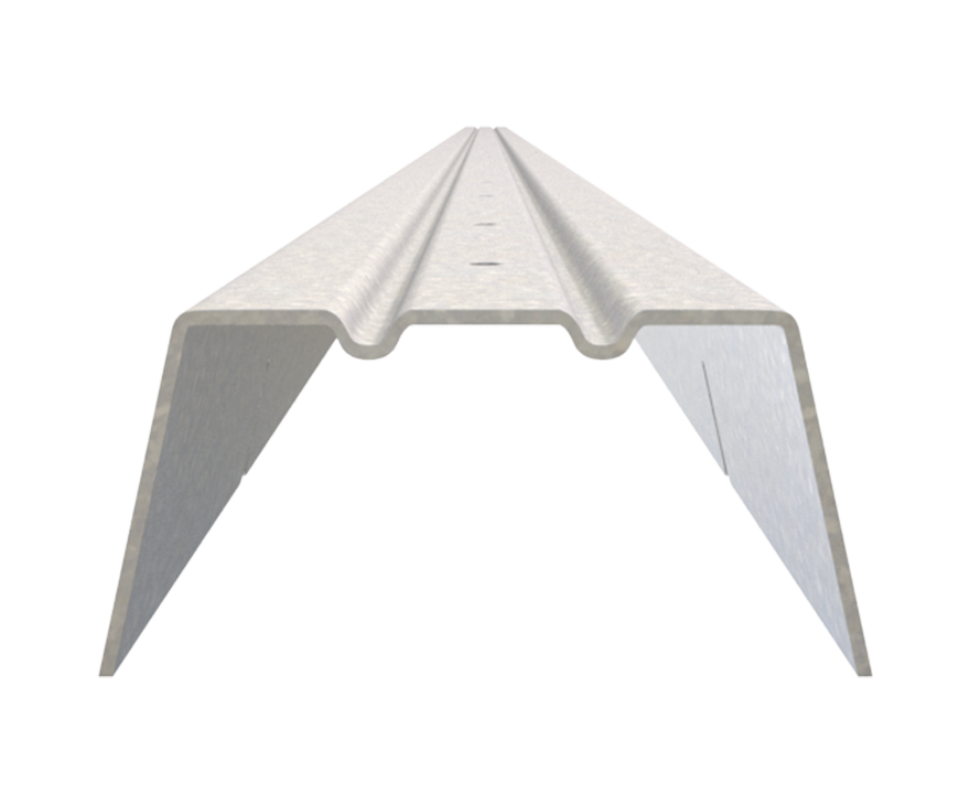
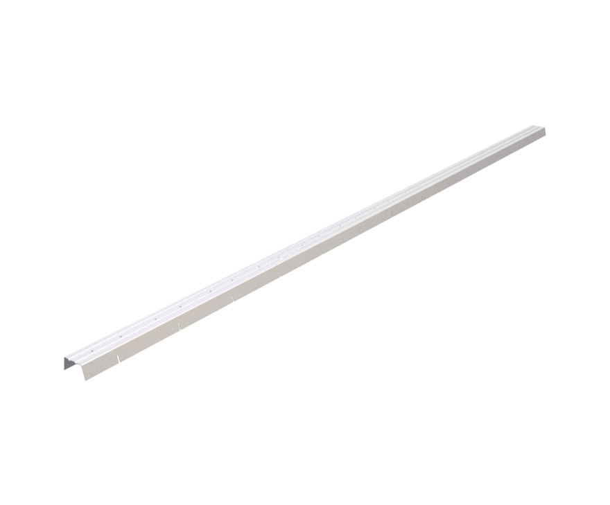
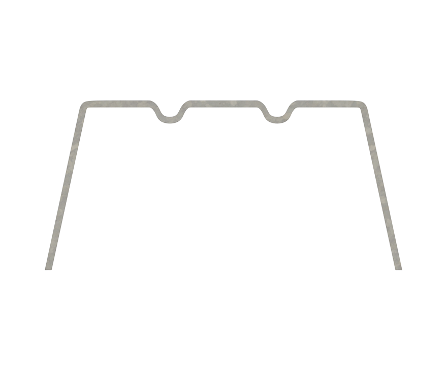
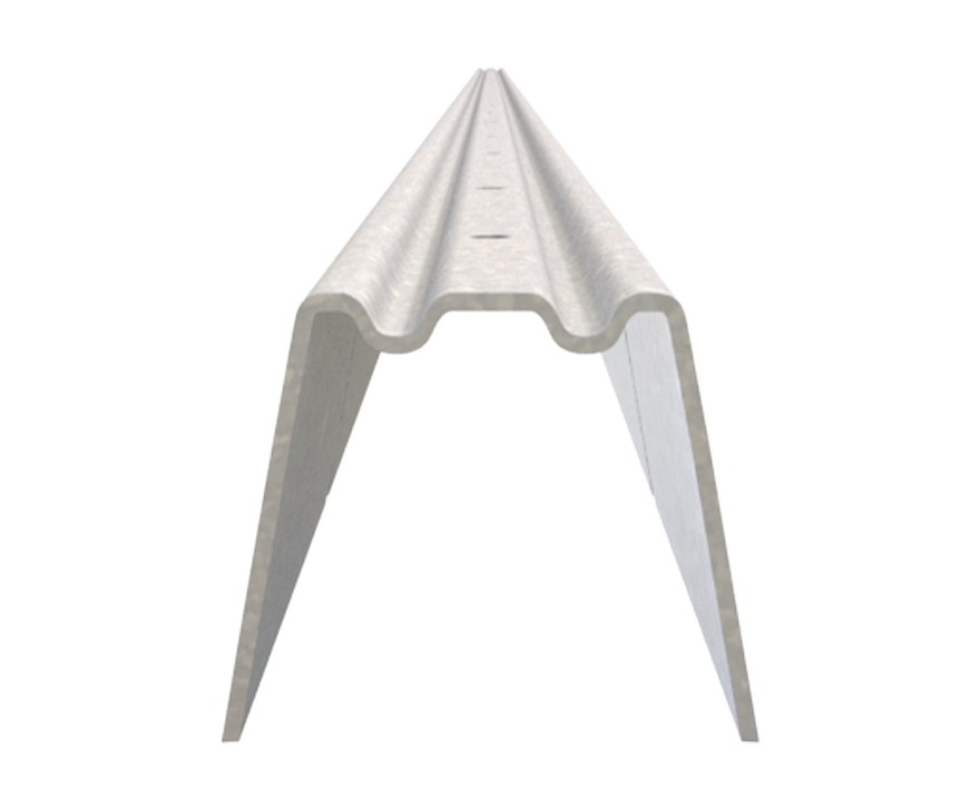
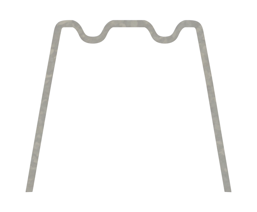
BridgeBar® replaces cold-rolled channel (CRC) for wall bridging. Unique grooves every 4” trap stud web to allow installers to space any type of wall layout. The grooves adjust to various stud thickness to trap the stud web for maximum strength. BridgeBar incorporates stiffeners to resist compressive loads through the plane of the wall. BridgeBar’s standard U-channel shape ensures use through ¾” and 1½” stud punchouts.
Features
- Fast installation
- Notches every 4″ accommodate 8″, 12″, 16″, 24″ centers
- No clamping
- No welding
- Load rated assembly
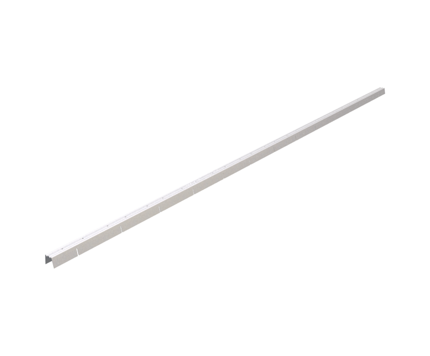
- 52-inch length allows for 4″ lap at joints for continuous walls
- Guide holes for placement when BridgeClip® is used
Order Information
| Designation | Qty/Box | Lbs/Box | Qty/Skid | Lbs/Skid |
| BB75 | 50 | 49 | 2,000 | 1,960 |
| BB150 | 50 | 70 | 1,250 | 1,750 |
Nomenclature
BridgeBar is available in ¾” and 1½” widths. Designations are BB75 and BB150.
Example: Stud with ¾” knockout
Designate: BB75
Material Composition
BB75: ASTM A1003/A1003M Structural Grade 33 (230) Type H, ST33H (ST230H): 33ksi (230MPa) minimum yield strength 45ksi (310MPa) minimum tensile strength, 28mil minimum thickness (22 gauge, 0.0295″ design thickness) with ASTM A653/A653M G60 (Z180) hot dipped galvanized coating.
BB150: ASTM A1003/A1003M Structural Grade 50 (340) Type H, ST50H (ST340H): 50ksi (340MPa) minimum yield strength, 65ksi (450MPa) minimum tensile strength, 33mil minimum thickness (20 gauge, 0.0346″ design thickness) with ASTM A653/A653M G90 (Z275) hot dipped galvanized coating.
Catalogs
|
|
For a full list of our product catalogs, specification sections, inspection checklists, and research reports please click here.
BridgeBar Downloads
BridgeBar® Applications
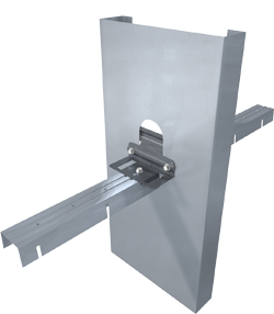
Wall Bridging Channel
Installation Instructions
- Run BridgeBar through stud punchouts.
- Locate grooves at bottom of punchout and press down into place.
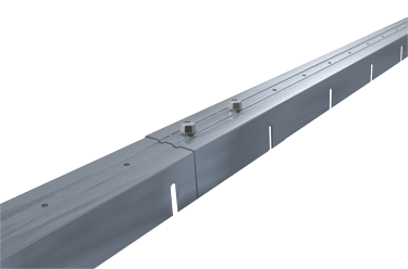
Lap Joints
Allowable Loads
Notes:
- Use BridgeClip® for a quick & easy method of securing BridgeBar to stud (when required)
- Resists compressive loads through the plane of the wall
- Use through ¾” and 1½” stud punchouts.
- Gross section properties are calculated based on the minimum dimensions of the cross section.
- Effective section properties and allowable loads for BridgeBar are calculated based on AISI S100-2007 Specification.
- Effective section modulus (Sxe) is calculated based on the minimum dimensions of the cross section.
- Effective area (Ae) and allowable axial load (Pa) are calculated based on the average dimensions of the cross section.
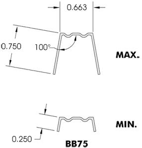
BB75 Section Properties
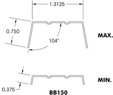
BB150 Section Properties
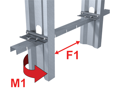
Load Direction
Allowable Screw Shear
When loads require attachment of BridgeBar to stud, consider the screw shear allowables below for connection of BridgeClip to stud and BridgeBar.
Follow us on Social Media


