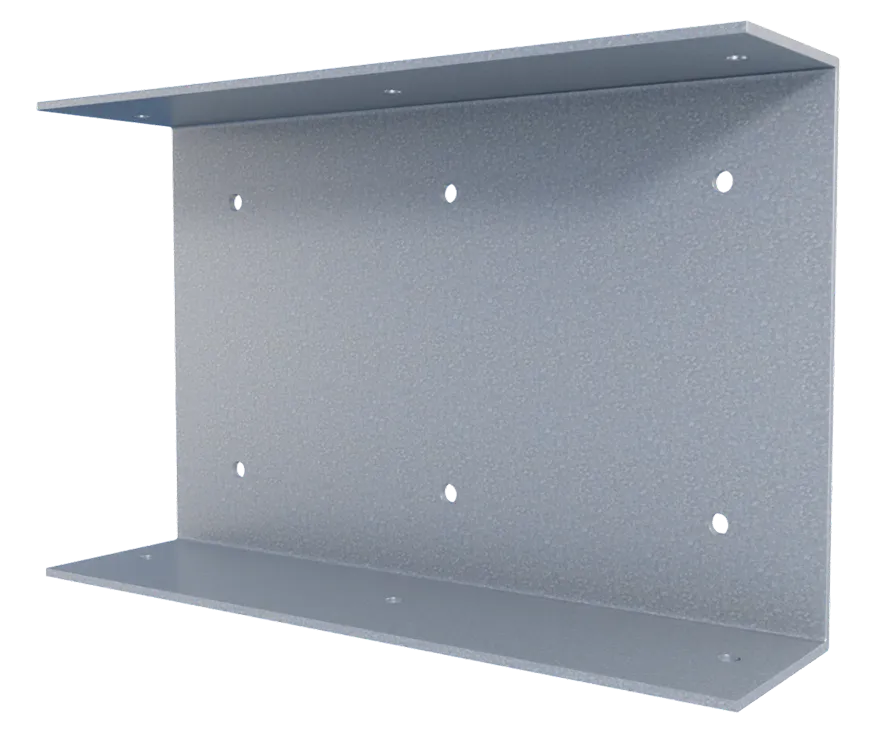
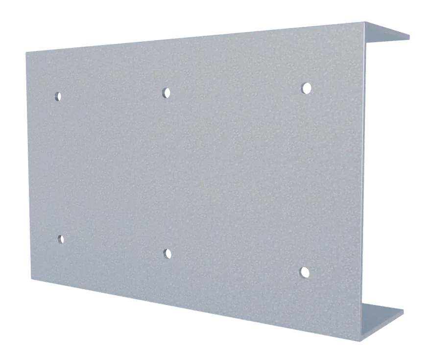
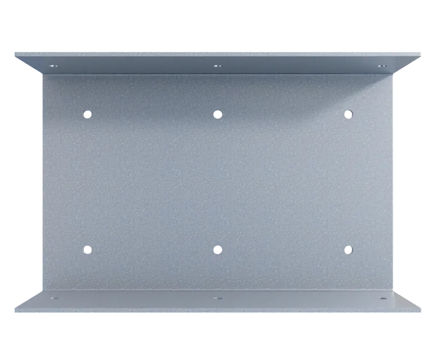
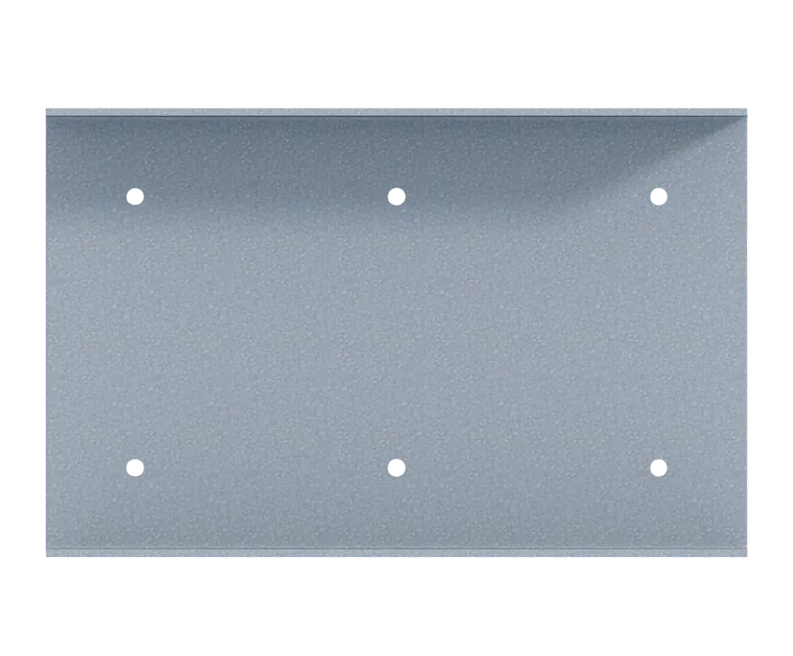
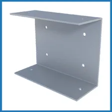
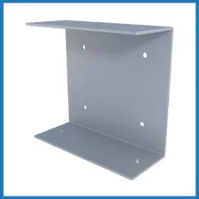
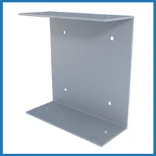
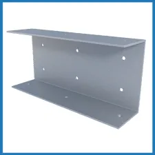
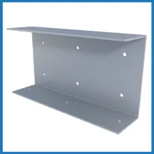
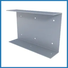
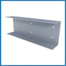
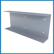
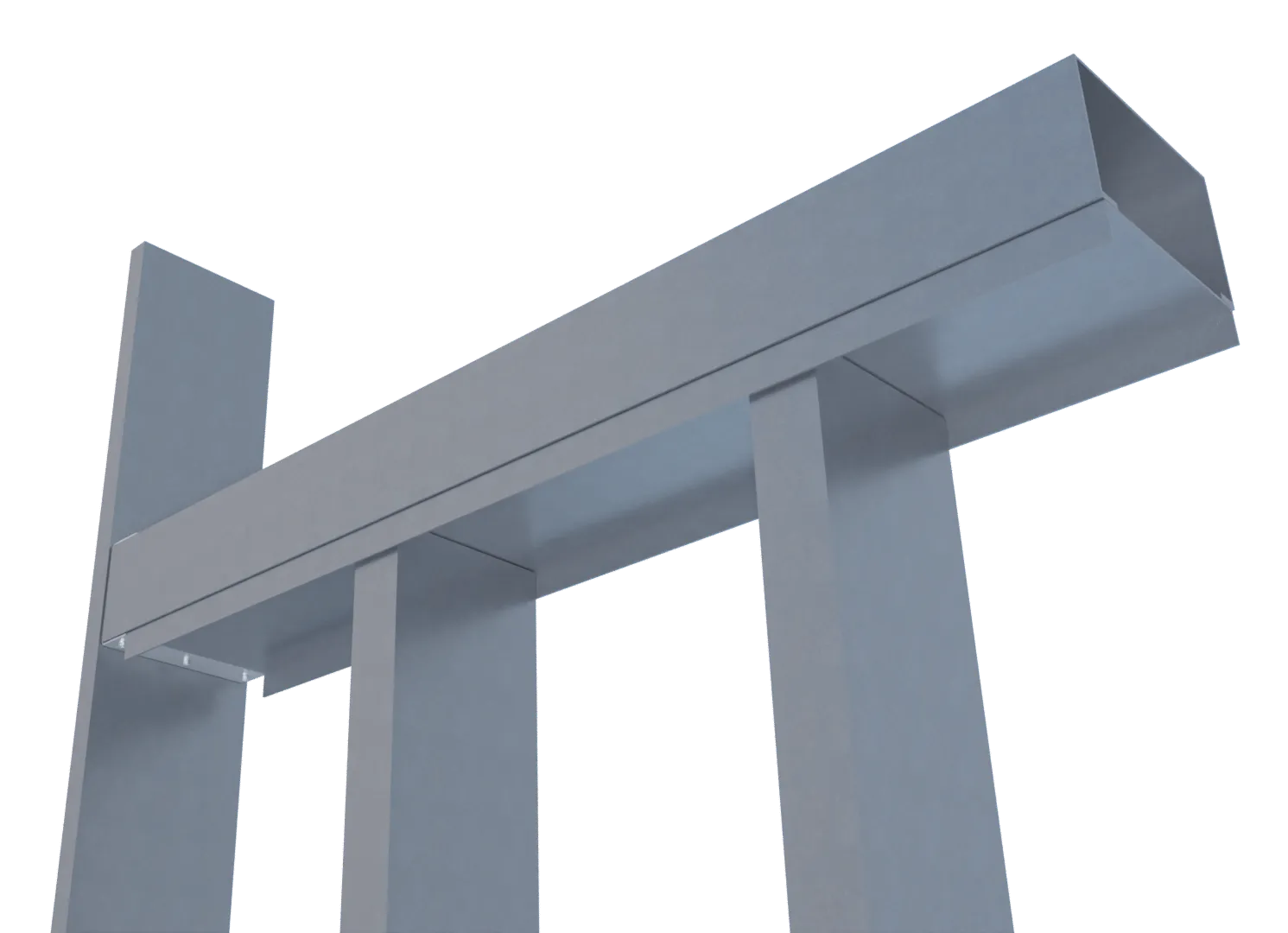
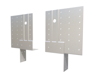
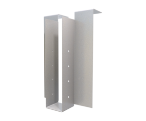
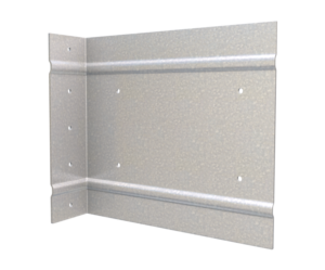
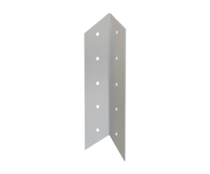
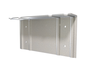
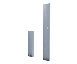
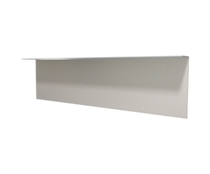
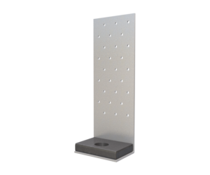
StiffClip® HS Header/Sill Clip
Features
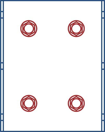
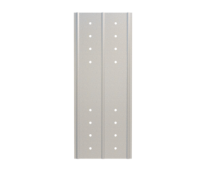
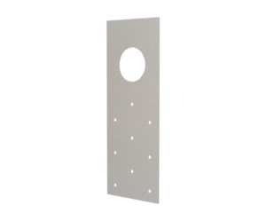
- Guide holes for connections to column and JamStud, box header or sill
- Resists vertical and horizontal loads
- Acts as a web stiffener
- Quick installation
- Reduces material (no jack studs or caps required)
- Reduces labor expenses
Material Composition
ASTM A1003 ST50H, Grade 50 (340MPa) minimum yield strength, 65 ksi (450 Mpa) minimum tensile strength, material thickness = 68mil (14gauge, 0.0713″ design thickness) G90 (Z275) hot-dipped galvanized coating.
Catalogs
TSN’s Product Catalogs are an essential resource for the design of cold formed steel. Developed by Engineers, the catalogs contain design data for members, connectors, and fasteners. StiffClip® HS can be found in the following Catalogs:
|
|
|


For a full list of our product catalogs, specification sections, inspection checklists, and research reports please click here.
Order Information
Nomenclature
StiffClip® HS is available for various headers/sills. To specify, multiply header/sill web depth by 100, followed by header/sill flange width multiplied by 100
Example: 6″ web depth and 2 ½” flange width
Designate: StiffClip® HS600-250
StiffClip® HS Downloads
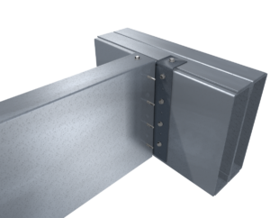
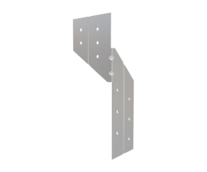
StiffClip® HS Applications

StiffClip® HS with JamStud® header
StiffClip® HS with JamStud® Sill
Installation Instructions
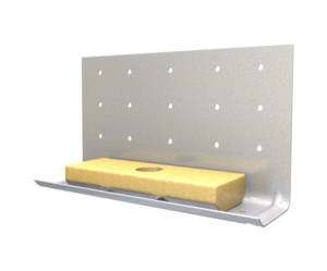
- Attach StiffClip® HS to stud through guide holes with approved fasteners
- Insert Header/Sill
- Attach StiffClip® HS to header/sill through guide holes with approved fasteners.
Allowable Loads
 4 Screws
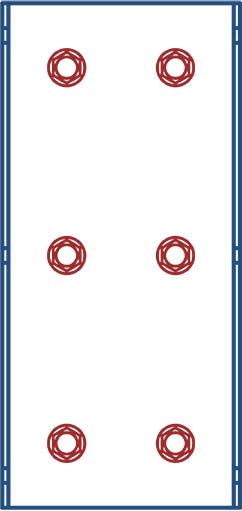 6 Screws
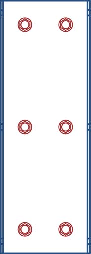 6 Screws4 Screws6 Screws6 Screws
Load Table Notes:
- Design loads are for attachment of StiffClip HS to the jamb. Use minimum (4) #10 screws for the attachment of the clip to the header or sill. Load tables reflect horizontal loads (F2) and vertical loads (F3).
- Design loads consider loads on the clip and #10 screw fasteners to the jamb web.
- Loads listed reflect force in a single direction. When multiple loads react on the connection, it is the responsibility of the designer to check the interaction of forces.
- Up to 1/4″ gap is allowed between the jamb and the end of the header/sill member.
- Allowable loads apply to 250, 300, and 350 flange sizes.
- Allowable loads have not been increased for wind, seismic, or other factors.
- For LRFD strengths contact TSN technical services.
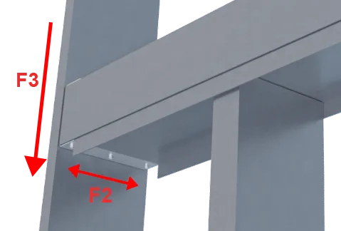
Load Direction
More Rigid Wall & Floor Connectors

Follow us on Social Media
