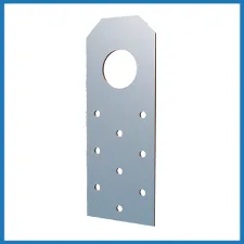
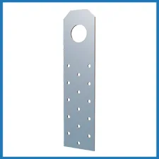
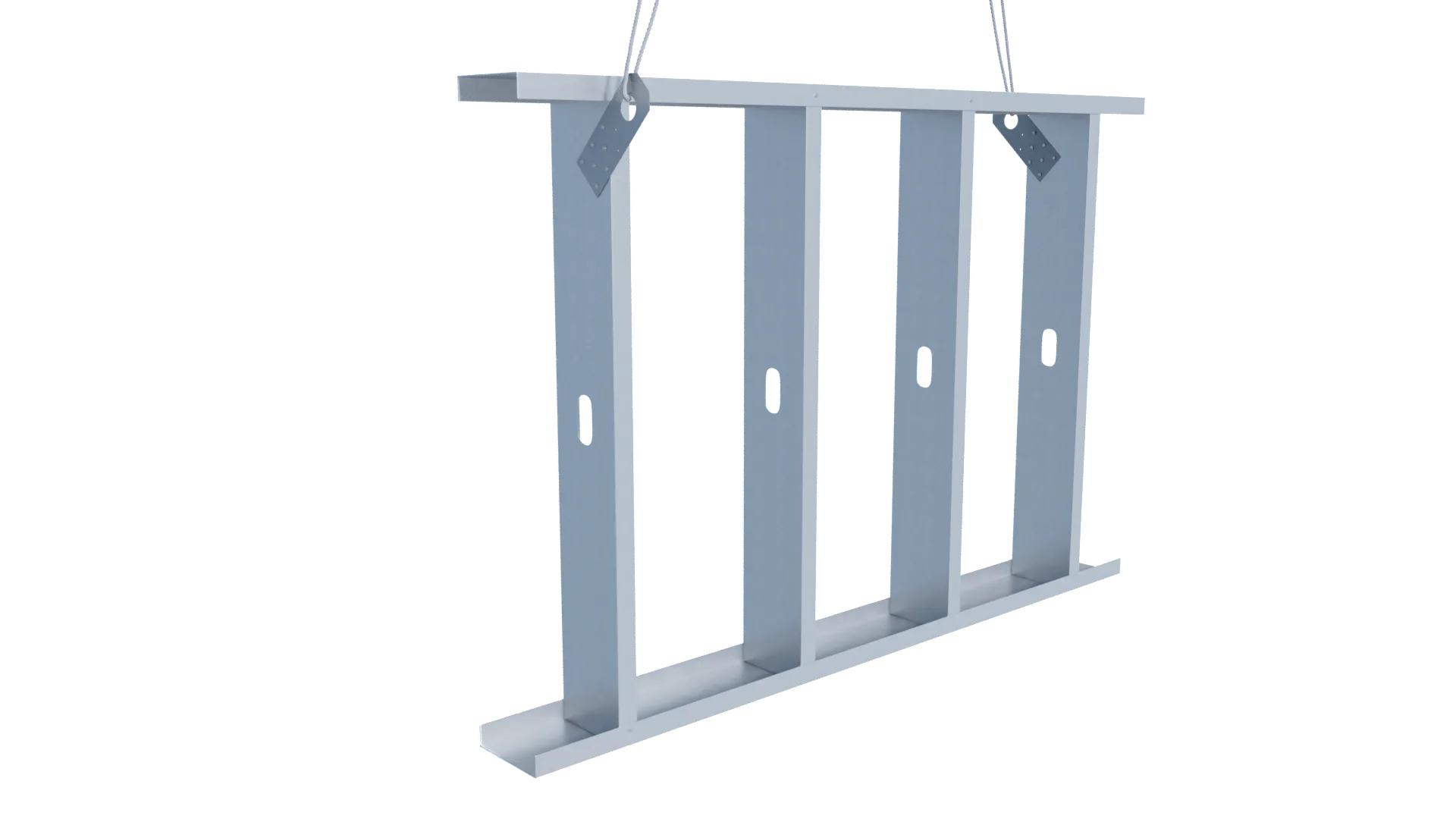
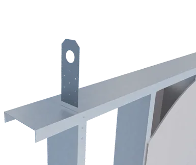
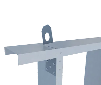
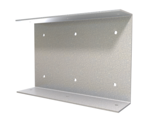
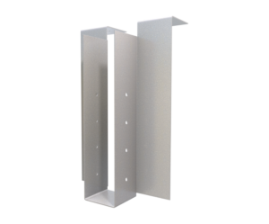
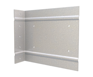
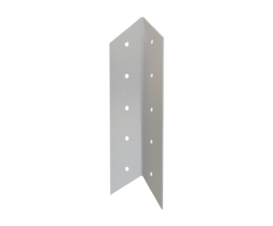
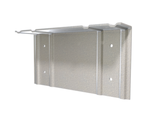
StiffClip® PLC Panel Lift Clip
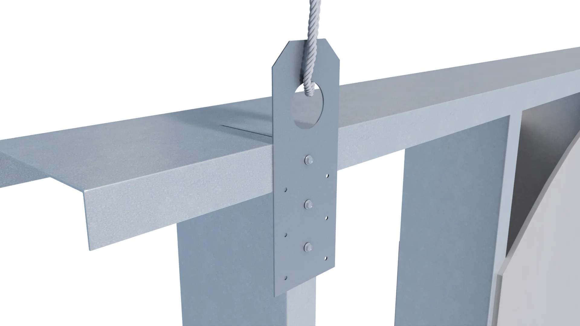
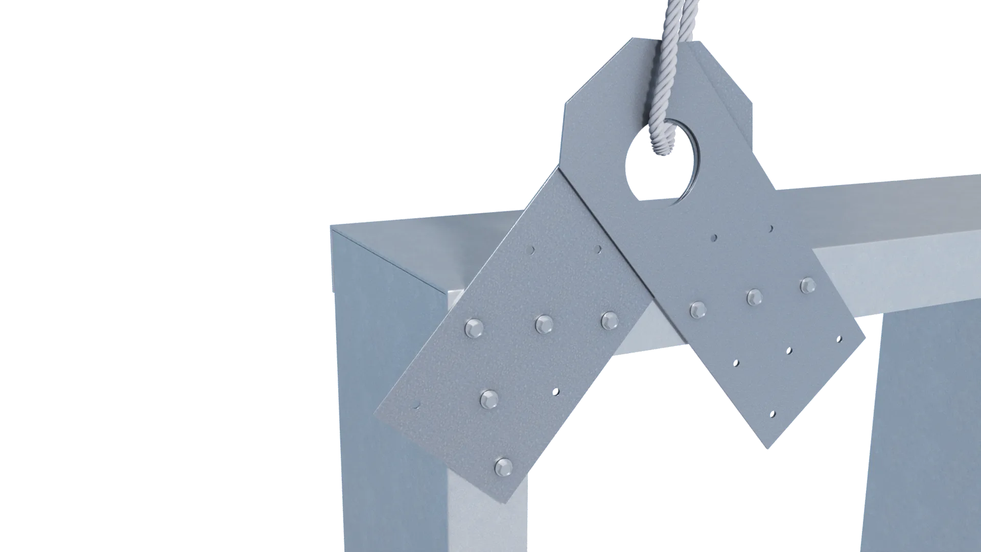
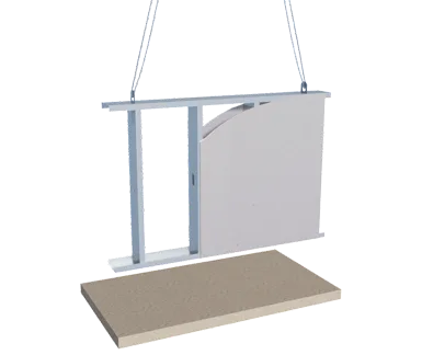
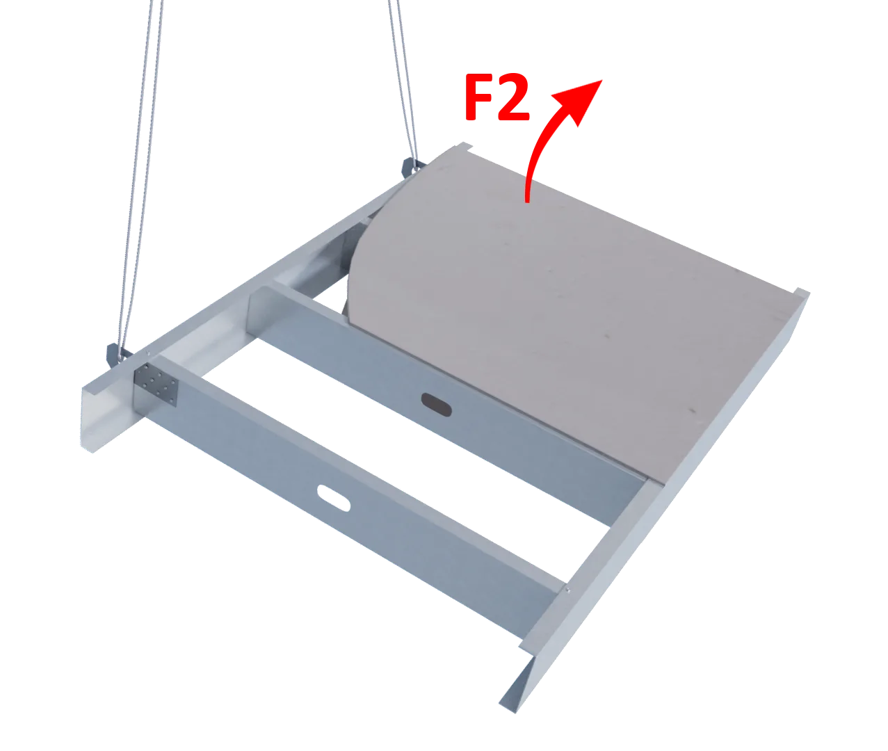
StiffClip® PLC assists with lifting and placing assembled wall panels with an overhead crane. Clip attaches to stud within panel with approved fasteners, extending through the top track to allow cables to be threaded through the large hole, and the assembled panel to be safely lifted into place.
Features
- Safely lift and place assembled wall components
- Attaches easily through pre-punched guide holes
- Utilizes only certified, 50ksi steel
- Adaptable for multiple configurations
Material Composition
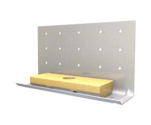
ASTM A1003/A1003M Structural Grade 50 (340) Type H, ST50H (ST340H): 50ksi (340MPa) minimum yield strength, 65ksi (450MPa) minimum tensile strength, 97mil minimum thickness (12 gauge, 0.1017” design thickness) with ASTM A653/A653M G90 (Z275) hot dipped galvanized coating.
Catalogs
TSN’s Product Catalogs are an essential resource for the design of cold formed steel. Developed by Engineers, the catalogs contain design data for members, connectors, and fasteners. StiffClip® PLC can be found in the following Catalogs:
|
|
|
For a full list of our product catalogs, specification sections, inspection checklists, and research reports please click here.

Order Information
PLC-8-97
PLC-12-97
Qty/Box
50
50
Lbs/Box
25
37
Qty/Skid
2,000
2,000
Lbs/Skid
1,000
1,480
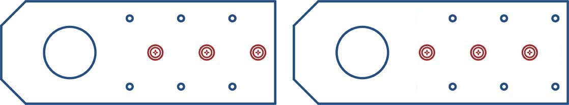
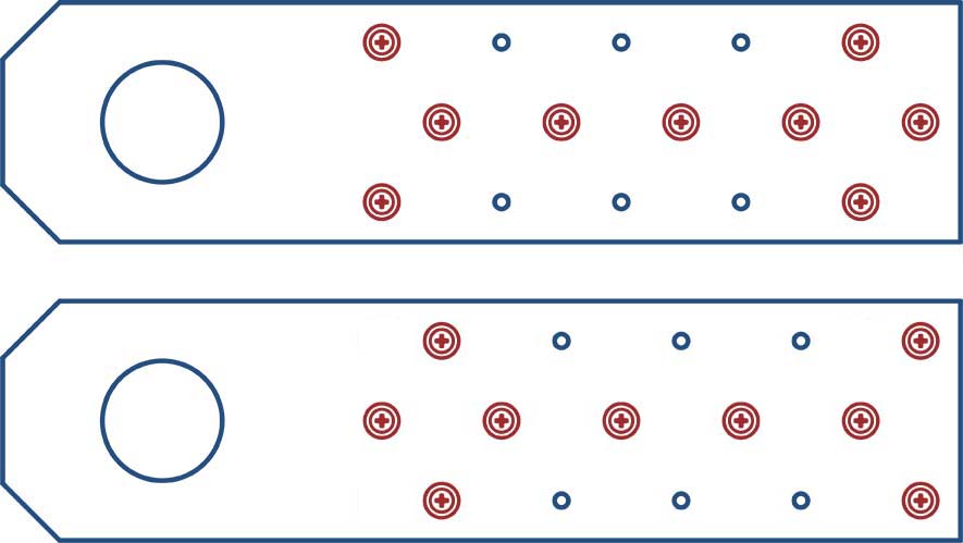
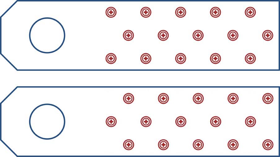
Nomenclature
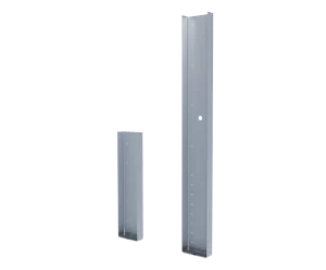
StiffClip PLC is available in two sizes and is designated by the length of the clip, followed by mil thickness (-97).
Example: 8″ connector
Designate: StiffClip® PLC-8-97
StiffClip® PLC Downloads
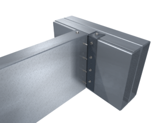
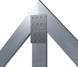
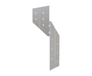
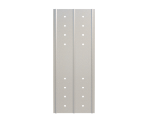
StiffClip® PLC Applications
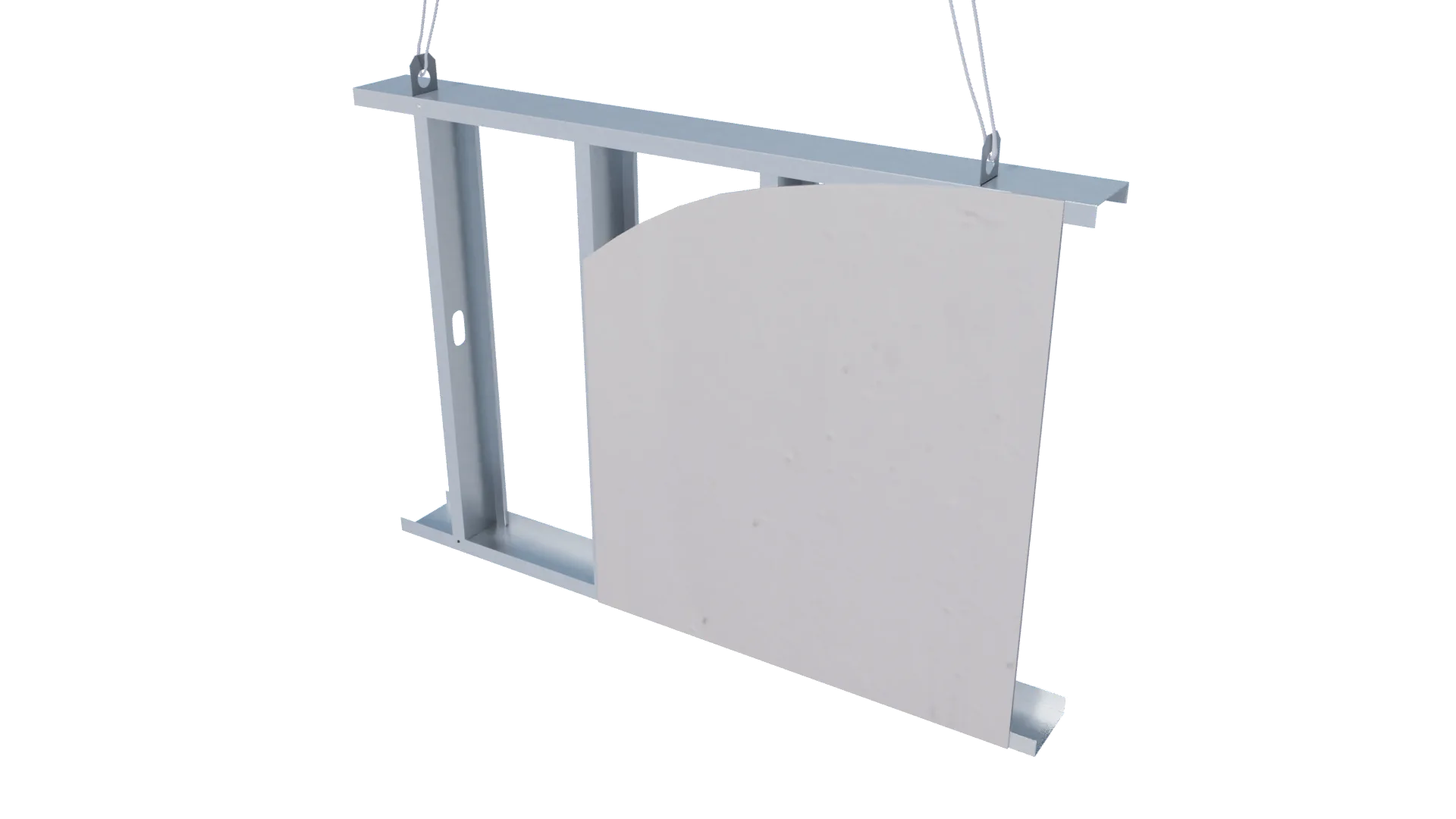
Lifting Panel into Position
Attachment to Wall at Intermediate Stud
Double Attachment to Wall at End Stud
Attachment to Stud Web
Installation Instructions

Step 1: Cut slot in top track of panel
Step 2: Insert PLC through slot
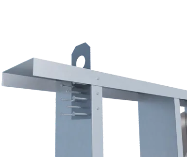
Step 3: Attach StiffClip® PLC to stud through guide holes with approved screws
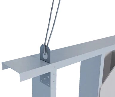
Step 4: Insert lifting cable through 1.5" hole
Step 5: Lift panel into place
Step 6: Trim top of clip flush with the top track of installed panel
Allowable Loads
33mil (20ga), 33ksi Stud
33mil (20ga), 50ksi Stud
43mil (18ga), 33ksi Stud
43mil (18ga), 50ksi Stud
54mil (16ga), 33ksi Stud
54mil (16ga), 50ksi Stud
68mil (14ga), 50ksi Stud
97mil (12ga), 50ksi Stud
Maximum Allowable Clip Load
F2 Load Direction
PLC-8-97
 3 Screws
106
153
158
228
222
320
329
329
329
1,156
F2 Load Direction
PLC-8-97
 6 Screws
306
441
455
658
641
924
949
949
949
1,156
F2 Load Direction
PLC-8-97
 9 Screws
373
537
554
800
779
1,125
1,154
1,154
1,154
1,156
F2 Load Direction
PLC-12-97
 5 Screws
166
239
247
356
347
501
514
514
514
1,156
F2 Load Direction
PLC-12-97
 9 Screws
237
341
352
509
495
715
734
734
734
1,156
F2 Load Direction
PLC-12-97
 15 Screws
517
745
768
1,110
1,081
1,156
1,156
1,156
1,156
1,156
33mil (20ga), 33ksi Stud
33mil (20ga), 50ksi Stud
43mil (18ga), 33ksi Stud
43mil (18ga), 50ksi Stud
54mil (16ga), 33ksi Stud
54mil (16ga), 50ksi Stud
68mil (14ga), 50ksi Stud
97mil (12ga), 50ksi Stud
Maximum Allowable Clip Load
F3 Load Direction
PLC-8-97
3 Screws531
765
789
1,140
1,110
1,361
1,361
1,361
1,361
1,361
F3 Load Direction
PLC-8-97
6 Screws1,062
1,361
1,361
1,361
1,361
1,361
1,361
1,361
1,361
1,361
F3 Load Direction
PLC-8-97
9 Screws1,361
1,361
1,361
1,361
1,361
1,361
1,361
1,361
1,361
1,361
F3 Load Direction
PLC-12-97
5 Screws885
1,275
1,315
1,361
1,361
1,361
1,361
1,361
1,361
1,361
F3 Load Direction
PLC-12-97
9 Screws1,361
1,361
1,361
1,361
1,361
1,361
1,361
1,361
1,361
1,361
F3 Load Direction
PLC-12-97
15 Screws1,361
1,361
1,361
1,361
1,361
1,361
1,361
1,361
1,361
1,361
Load Table Notes
- Design loads consider loads on the clip and #10 screw fasteners to steel framing.
- Spacing between clips to be controlled by the weight of panel and presence of a spreader bar or a load distribution member
- For screw patterns other than standard patterns shown, contact TSN technical services.
- For LRFD strengths contact TSN technical services.
F2 Load Direction
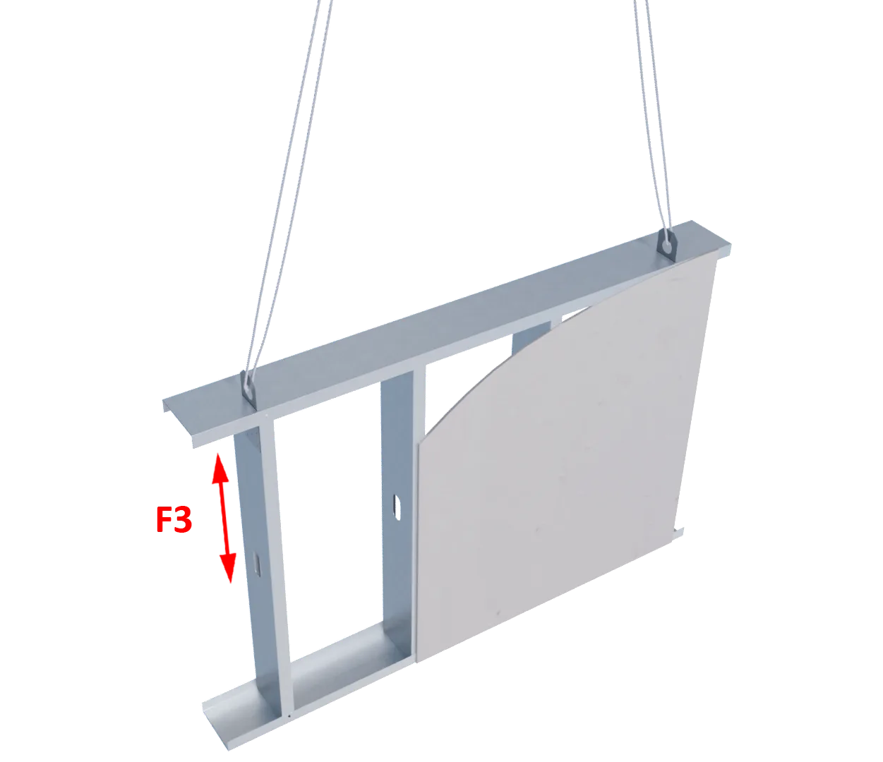
F3 Load Direction
Related Projects

More Rigid Wall & Floor Connectors
Follow us on Social Media
