MasterClip® VLB Exterior Slab Bypass
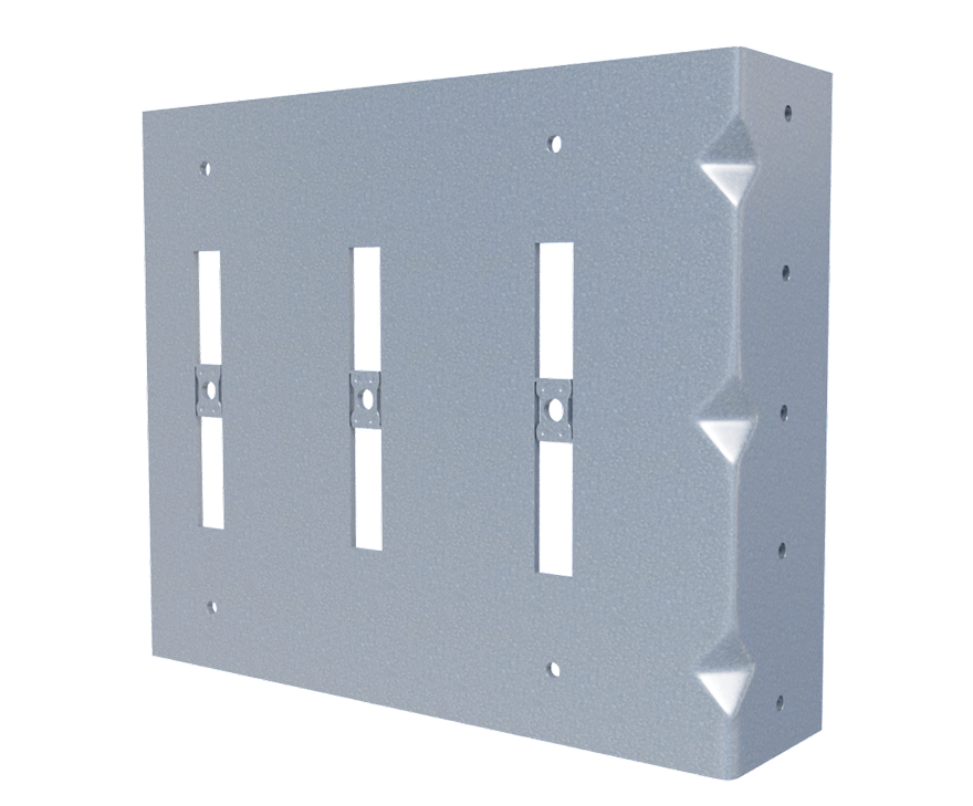
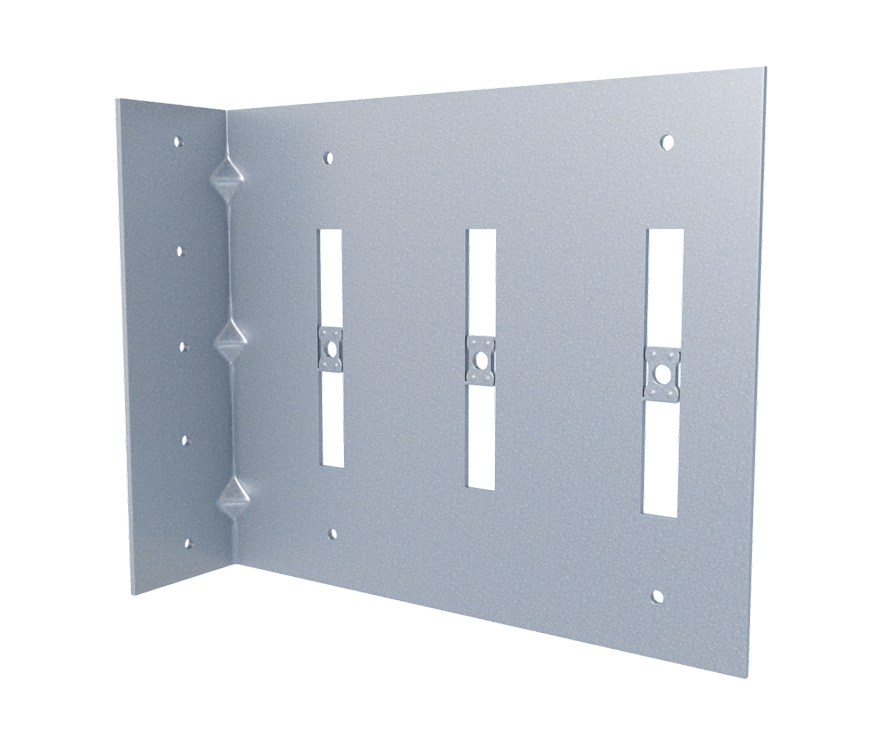
Easily connect exterior cold-formed steel curtain wall studs to the slab, bypassing the primary structure. The MasterClip VLB’s dual-purpose design allows it to be installed as a rigid connection to resist vertical & horizontal loads or a vertical deflection connection.
Its patented Integrated Break-Away Step Bushings provide friction-free motion for a smooth vertical deflection (slide) connection providing up to 2” deflection (1” up & 1” down). Simplify ordering process & inventory with a single clip for rigid & deflection applications.
Features
- Load-rated positive mechanical attachment at each stud
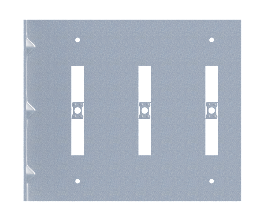
- Patented Integrated Break-Away Step Bushings provide friction-free motion for smooth vertical deflection
- Eliminates loose friction-held assemblies, heavy deep-leg track, & the top row of wall bridging/strapping
- Load-rated #12 screws provided for vertical deflection connection to stud web
- Manufactured with certified, 68mil, 50ksi cold-formed steel
Material Composition
Catalogs
TSN’s Product Catalogs are an essential resource for the design of cold formed steel. Developed by Engineers, the catalogs contain design data for members, connectors, and fasteners. MasterClip® VLB can be found in the following Catalogs:
|
|
|

For a full list of our product catalogs, specification sections, inspection checklists, and research reports please click here.
Blast & Seismic Design

US Patents #8,181,419, #8,683,770, & #10,132,341
Order Information
Nomenclature
MasterClip VLB is designated by type (VLB), followed by stud depth in inches multiplied by 100.
Example: 6″ stud
Designate: MasterClip® VLB600
MasterClip® VLB Downloads

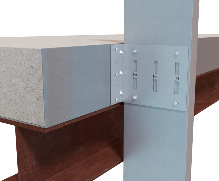
MasterClip® VLB Applications
The unique design of MasterClip allows it to be installed either as a vertical deflection connection or a rigid connection. The attachment of MasterClip to the primary structure may be made with PAFs, screw/bolt anchors or welds and is dependent upon the base material (steel, concrete or CMU) and the design configuration.
Curtain Wall Slab Bypass as a Vertical Deflection Connection
Curtain Wall Slab Bypass as a Rigid Connection
MasterClip® VLB Installation Instructions
- Place the MasterClip VLB slide angle against structural pour stop.
- Attach VLB to the structure with required fasteners, as designed:
-
-
- For a Vertical Deflection Connection: Fasten VLB to the stud with provided screws through Integrated Break-Away Step Bushings.
- For a Rigid Connection: Fasten VLB to the stud with required screws through pre-drilled guide holes.
-
-
MasterClip® VLB Allowable Loads:
Load Table Notes:
- MasterClip VLB resists in plane of wall (F1), horizontal (F2), and vertical (F3) loads when used as a rigid connector.
- MasterClip VLB resists in plane of wall (F1) and horizontal (F2) loads when used as a deflection connector.
- Allowable loads have not been increased for wind, seismic, or other factors.
- Design loads consider loads on the clip and #12 screw fasteners to the stud web.
- Three #12 screws are provided with each connector (based on number of integrated breakaway step bushings). Load requirements don’t always require the use of all screws provided.
- Three slots are standard in 6″ and higher web depths to accommodate construction tolerances. Use of a 3rd screw and bushing is dependent upon load requirements.
- Total vertical deflection up to 2″ (1″ up and 1″ down).
- Guide holes in the 1-1/2″ leg measure 0.141″ in diameter.
- Fasten within 3/4″ of the angle heel (centerline of the 1-1/2″ leg) to minimize eccentric load transfer.
- Fasteners attaching clips to structure should be installed symmetrically around the center line of the clip. The allowable load of the clip may be reduced if fasteners are not installed symmetrically.
- Allowable load tables incorporate eccentric loading of fasteners. Values with a welded connection may increase.
- Torsional effects are considered on the screw group for F3 allowable loads. It is assumed that half of the torsional moment is taken by the connection to the structure and half is taken by the screw connection to the stud.
- Loads listed reflect force in a single direction. When multiple loads react on the connection, it is the responsibility of the designer to check the interaction of forces.
- For LRFD strengths contact TSN technical services.
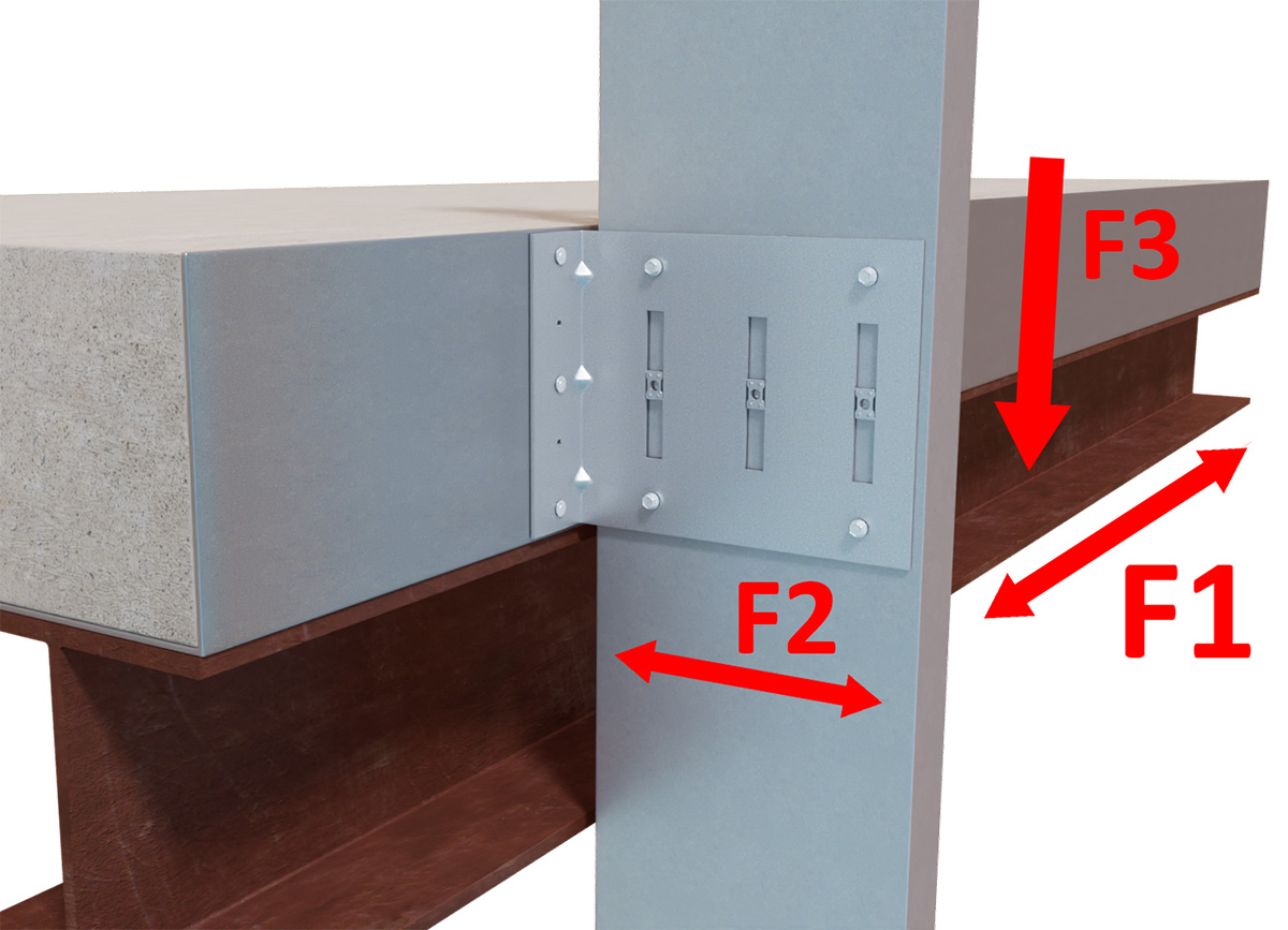
Load Directions
Rigid Connection: F1, F2, & F3 Load Directions
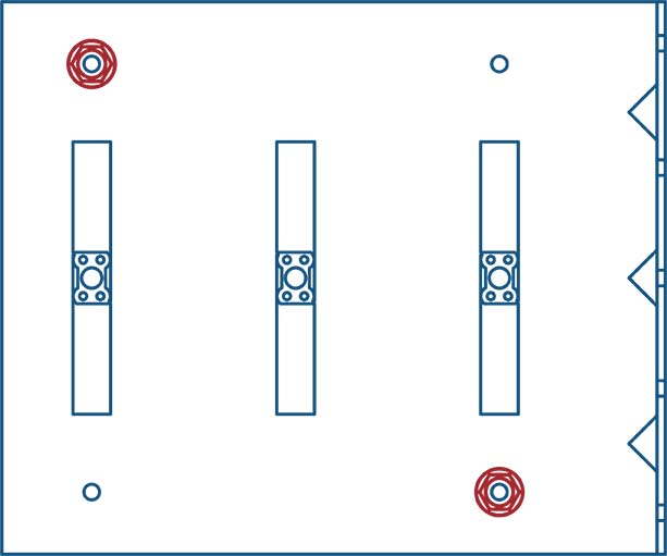 2 screws
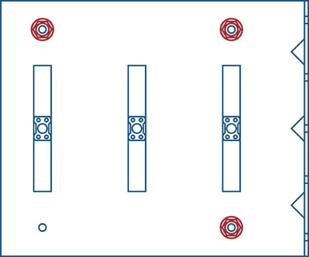 3 or 4 screws
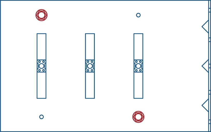 2 screws
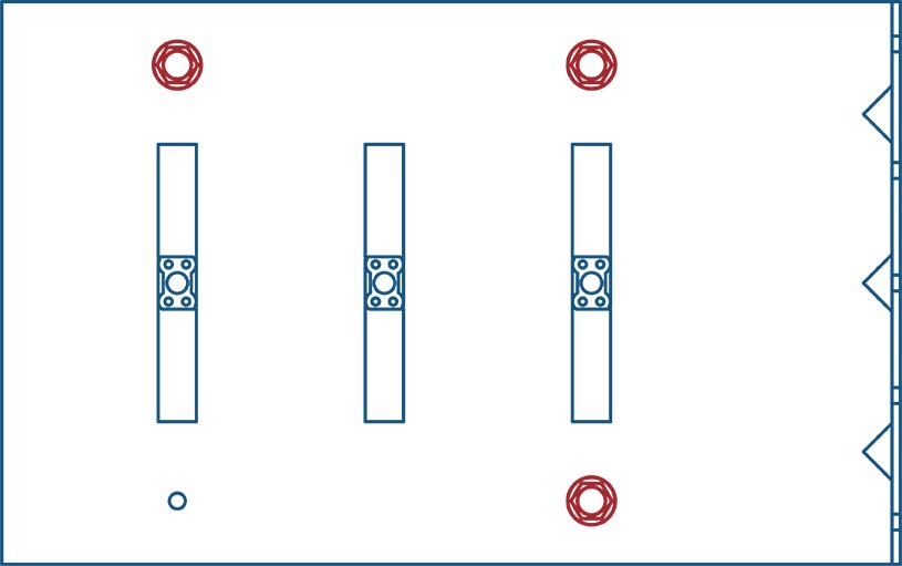 3 or 4 screws2 screws3 screws
 4 screws2 screws3 screws4 screws2 screws3 screws
 4 screws
Vertical Deflection: F1 & F2 Load Directions
2 screws3 screws2 screws3 screws2 screws3 screwsFollow us on Social Media
