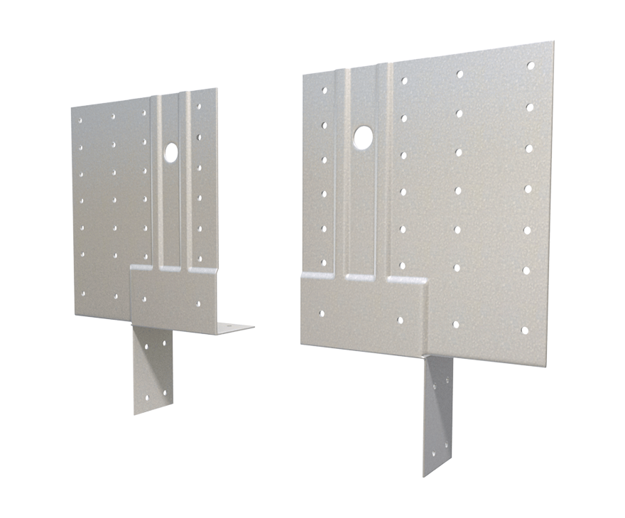
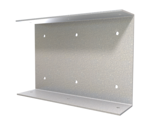
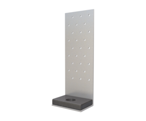
StiffClip® HE Header Clip
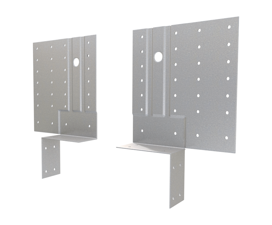
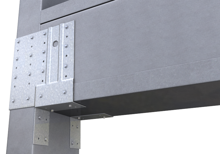
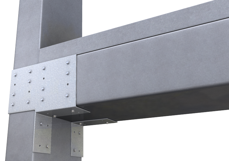
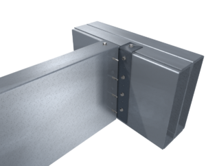
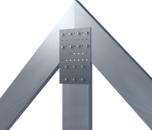
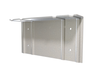
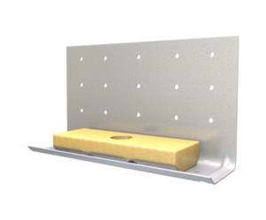
The StiffClip HE series is used when connecting either beams to columns or headers to jambs. StiffClip HE transfers horizontal and large vertical loads from the beam to the column while incorporating a small shelf tab for alignment of JamStud® or box header during installation.
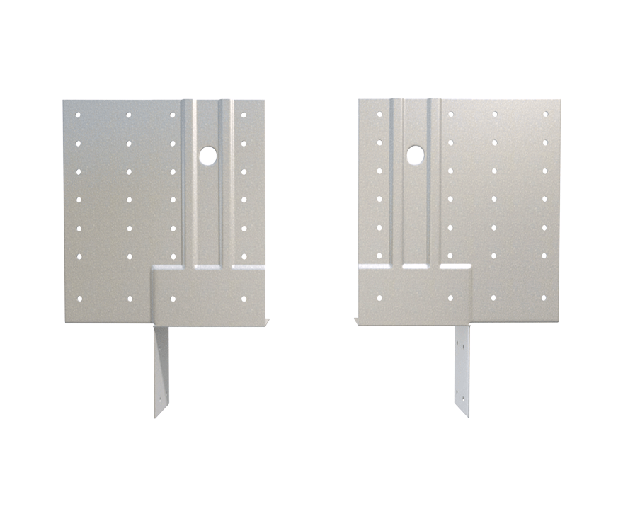
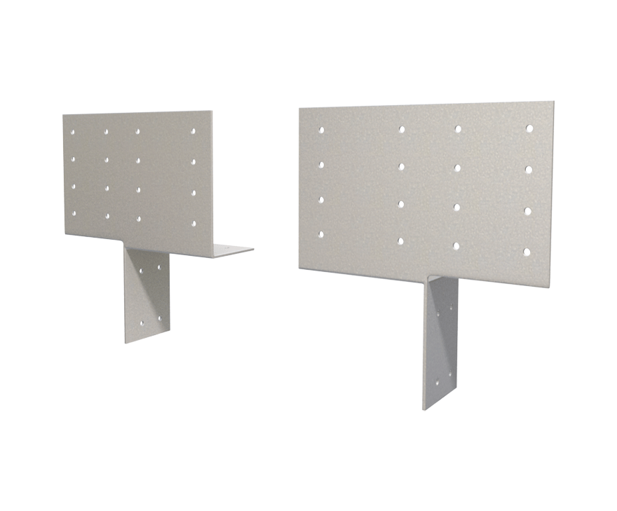
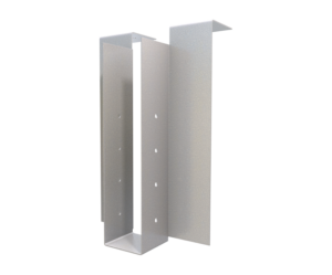
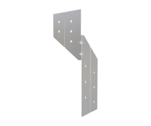
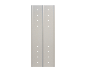
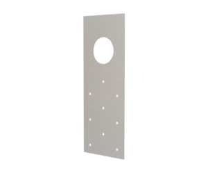
StiffClip HE(L) and HE(H) are designed to be used with typical box headers and incorporate stiffened ribs to protect the header ends from the effects of web crippling. StiffClip HE(S) is designed to be used with a single TSN JamStud as the header member.
Features
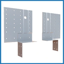
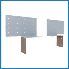
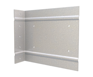
- Guide holes for connections to column and JamStud or box header
- Resists vertical and horizontal loads
- Acts as a web stiffener
- Tabs to hold header during installation
- Reduces material (no jack studs or caps required)
- Reduces labor expense
- Extensively tested
Material Composition
HE(L): ASTM A1003/A1003M Structural Grade 50 (340) Type H, ST50H (ST340H): 50ksi (340MPa) minimum yield strength, 65ksi (450MPa) minimum tensile strength, 43mil minimum thickness (18 gauge, 0.0451” design thickness) with ASTM A653/A653M G90 (Z275) hot dipped galvanized coating.
HE(H) & HE(S): ASTM A1003/A1003M Structural Grade 50 (340) Type H, ST50H (ST340H): 50ksi (340MPa) minimum yield strength, 65ksi (450MPa) minimum tensile strength, 68mil minimum thickness (14 gauge, 0.0713” design thickness) with ASTM A653/A653M G90 (Z275) hot dipped galvanized coating.
Catalogs
TSN’s Product Catalogs are an essential resource for the design of cold formed steel. Developed by Engineers, the catalogs contain design data for members, connectors, and fasteners. StiffClip® HE can be found in the following Catalogs:
|
|
|
For a full list of our product catalogs, specification sections, inspection checklists, and research reports please click here.
Blast & Seismic Design
US Patents #7,634,889
Order Information
Nomenclature
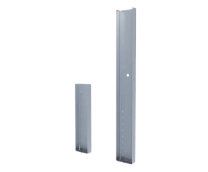
StiffClip® HE is available in two thicknesses. The StiffClip HE(L) is 43mil (18ga), and the StiffClip HE(H) & HE(S) are 68mil (14ga).
* Clips are packaged as pairs. Two left-hand and two right-hand clips attach the complete header to the jamb
StiffClip® HE Downloads

StiffClip® HE Applications
The unique design of MasterClip allows it to be installed either as a vertical deflection connection or a rigid connection. Attachment to the primary structure may be made with a PAF, screw/bolt anchors, or weld and is dependent upon the base material (steel or concrete) and the design configuration.
HE(L) or HE(H) with Boxed Header
HE(S) with TSN's JamStud® Header
StiffClip® HE Installation Instructions
- Attach StiffClip HE to jamb with required number of screws.
- Place header on shelf tabs of each StiffClip HE and attach clip to header with required number of screws.
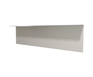
- Attach shelf ledge to header with required number of screws (if specified).
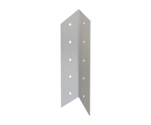
- Attach bottom angle to jamb with required number of screws (if specified).
StiffClip® HE Allowable Loads
Notes:
- Torsional effects are considered on screw group for F2 & F3 allowable loads. It is assumed that half of the torsional moment is taken by the connetion on one side and half is taken by the connection on the other side of the clip.
- Attachment to stud is made with screws symmetrically placed. All guide holes may not require fasteners. Fastener amount determined by designer.
- Allowable loads have not been increased for wind, seismic, or other factors.
- The minimum combination of steel thickness and yield strength must be used when determining the maximum design load.
- Design loads listed consider both loads on the clip and the #10 screws fastened to the jamb and header members.
- For LRFD strengths contact TSN technical services.
* Refer to screw patterns below.
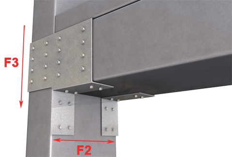
Load Directions
Screwed Connection – Single Clip: F2 & F3 Load Directions
Welded Connection – Single Clip: F3 Load Direction
Notes:
- The standard StiffClip HE(H) clip does not include all four large holes in the web of the clip. Special orders for these clips can be made by request.
- Allowable F3 welded values do not apply for the 43mil (18ga) StiffClip (HE(L).
- StiffClip HE(H) allowable F3 welded values are applicable to clips with welds around the perimeter of the single 1/2″ diameter hole, three 3/8″ diameter holes, and along each side of the clip. Weld size is not to exceed double the material thickness of the header or jamb, or 1/8″. Care should be taken to not burn through the material.
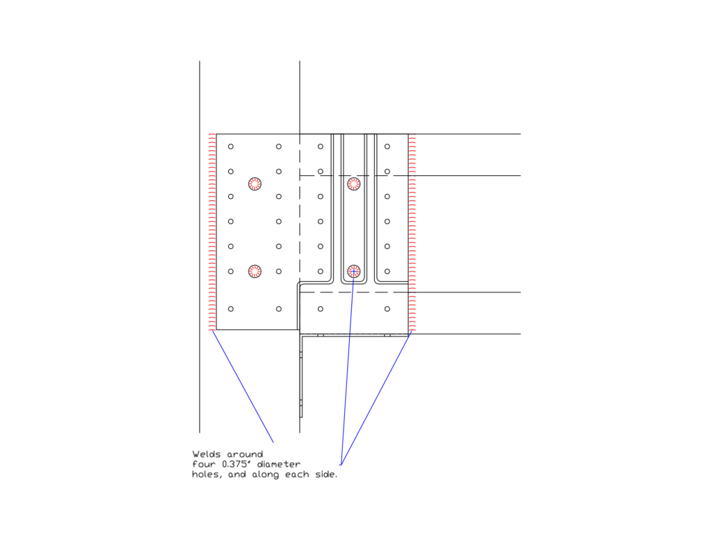
Weld Diagram
1/8″ weld around three 3/8″ diameter holes, one 1/2″ diameter hole, with 1/8″ welds along each side.
Related Projects


More Rigid Wall & Floor Connectors
Follow us on Social Media
