
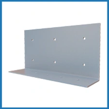
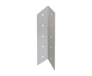
StiffClip® AL Multi-purpose Angle
Features
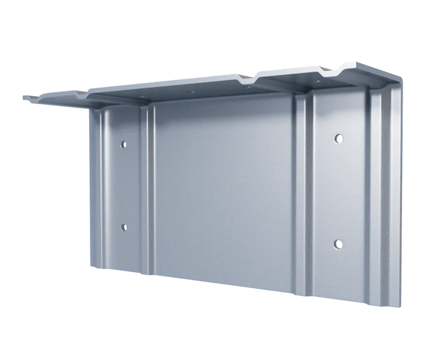
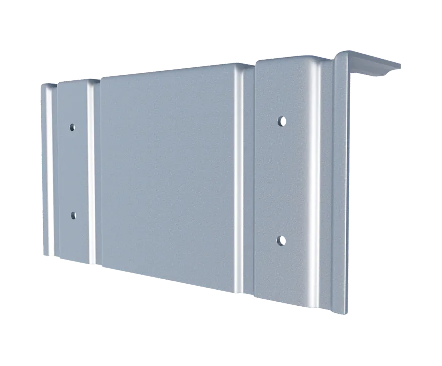
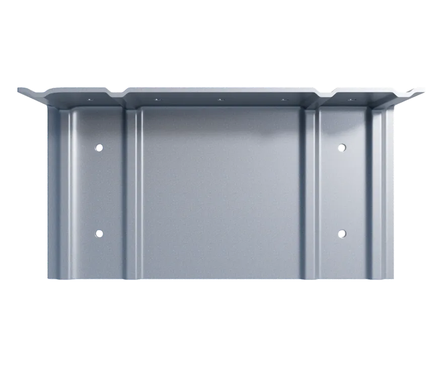
- Guide holes for fast and accurate connections
- Stiffeners for additional strength
- Manufactured from certified, 50ksi steel
- No labor spent cutting scrap angle
- Used in a variety of applications
- Extensively tested (reduces liability concerns associated with use of untested, miscellaneous untraceable material)
Material Composition
Catalogs
TSN’s Product Catalogs are an essential resource for the design of cold formed steel. Developed by Engineers, the catalogs contain design data for members, connectors, and fasteners. StiffClip® AL can be found in the following Catalogs:
|
|
|
For a full list of our product catalogs, specification sections, inspection checklists, and research reports please click here.
Order Information
Nomenclature
StiffClip AL is available for varioius stud depths. To specify, multiply stud depth by 100.*
Example: 6″ stud depth
Designate: StiffClip® AL600
* The AL362 fits 3 ⅝” and 4” member depths.
** Stiffening ribs are not present in the AL800.
StiffClip® AL Downloads




StiffClip® AL Applications
The attachment of StiffClip to the primary structure may be made with PAFs, screw/bolt anchors or weld and is dependent upon the base material (steel or concrete) and the design configuration.
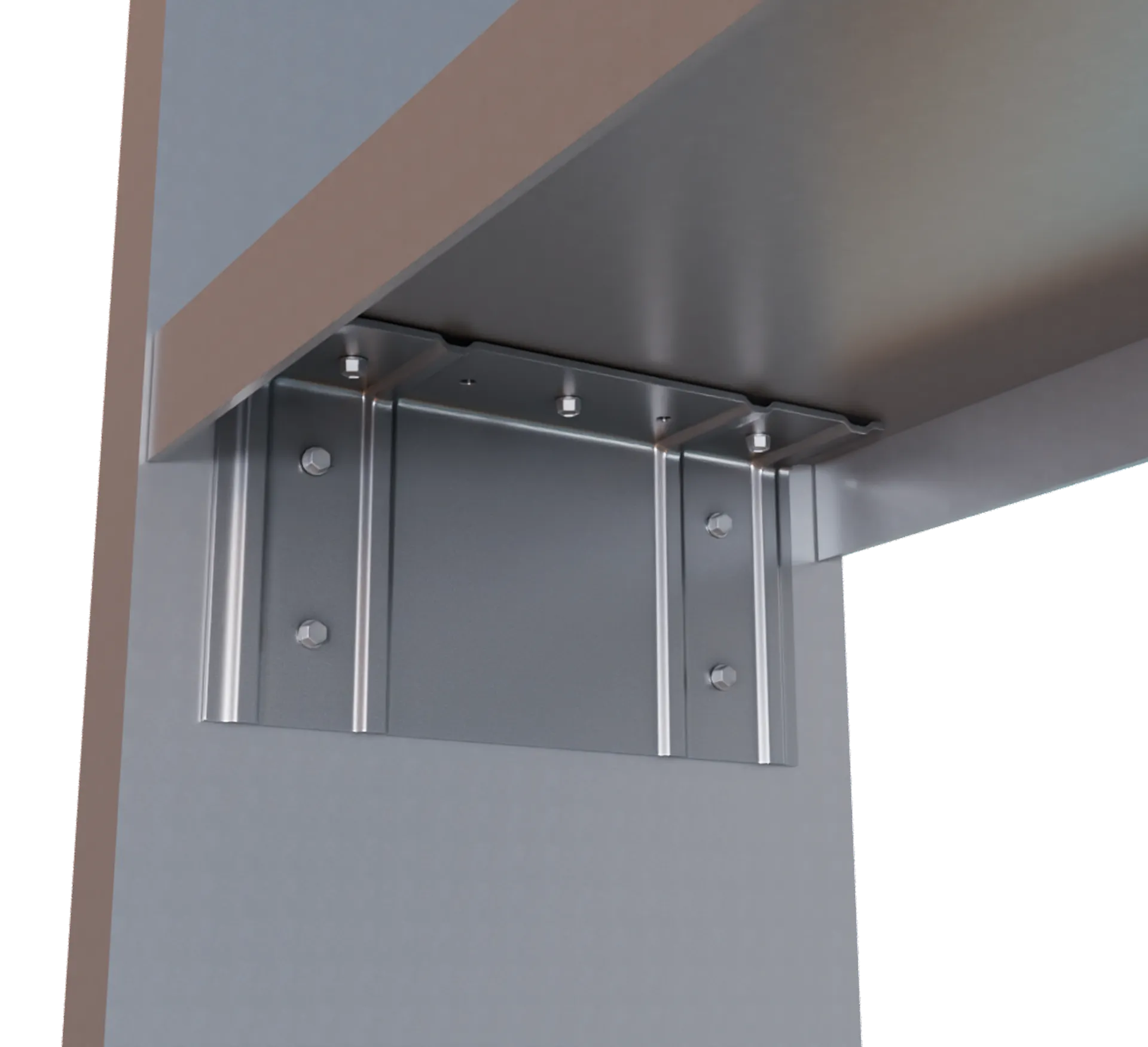
All Purpose Rigid Connector - Window Sill
Installation Instructions
- Specified #12 screws are attached to member through pre-drilled guide holes in the 3.125” leg.
- Attach short (1.5”) leg to structure/member either utilizing the pre-drilled guide holes or with weld (attachment through short leg is engineered by others).
- If pre-drilled holes are not able to be utilized, follow fastener manufacturer recommendations for screw placement.
Allowable Loads
Load Table Notes:
- StiffClip AL is tested to resist loads in horizontal, vertical, and lateral directions.
- Allowable load tables incorporate eccentric loading of fasteners attached 3/4″ from the heel of the clip. Values with welded connection may increase.
- Allowable loads are for attachment through 3″ leg only. Attachment through 1-1/2″ leg should be engineered. Reference Material Composition above for calculation purposes.
- Loads listed reflect force in a single direction. When multiple loads react on the connection, it is the responsibility of the designer to check the interaction of forces.
- Torsional effects are considered on screw group for F2 and F3 allowable loads. It is assumed that half of the torsional moment is taken by the connection in the short leg and half is taken by the connection in the long leg of StiffClip AL.
- Allowable loads have not been increased for wind, seismic, or other factors.
- All guide holes may not require fasteners. Number of fasteneres used is to be determined by designer.
- Stiffening ribs are not present in StiffClip AL800.
- For LRFD strengths contact TSN technical services.

Load Direction
Related Projects




More Rigid Wall & Floor Connectors
Follow us on Social Media