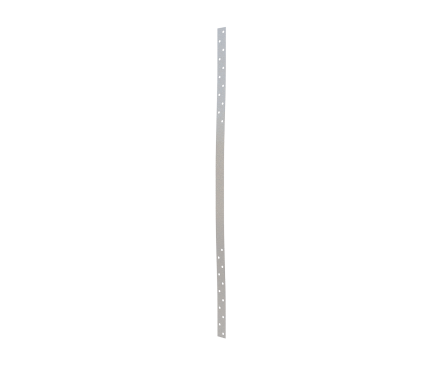
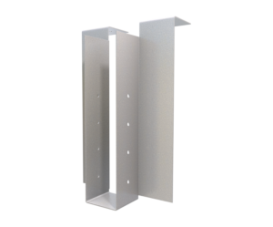
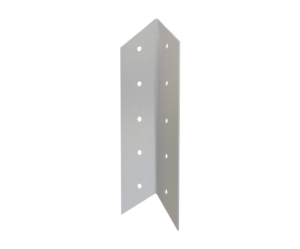
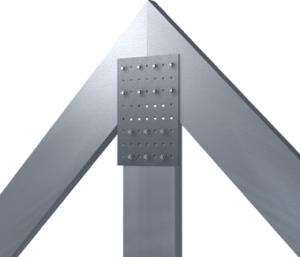
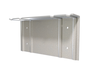
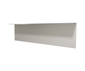
StiffClip® FS Uplift Transfer Clip
Features
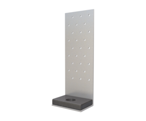
- Mill certified 50ksi steel
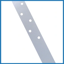
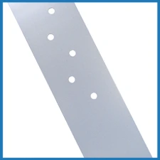
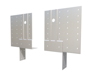
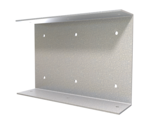
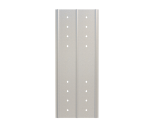
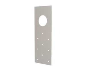
- Guide holes for attachment to wall studs (0.172” dia.)
- Structurally load tested
Material Composition
Catalogs
TSN’s Product Catalogs are an essential resource for the design of cold formed steel. Developed by Engineers, the catalogs contain design data for members, connectors, and fasteners. StiffClip® FS can be found in the following Catalogs:
|
|
|

For a full list of our product catalogs, specification sections, inspection checklists, and research reports please click here.
Order Information
Available Thickness
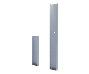
Nomenclature
StiffClip FS is designated by the width of the strap in inches followed by strap thickness in mils.
Example: 16ga, 2¾” strap, 24” long
Designate: StiffClip® FS275-54-24
* Guide holes located 1/2″ from each end, with ⅜” edge distance at 2″ o.c. staggered for FS125 and 0.75″ edge distance at 2″ o.c. staggered for FS275. Additional guide holes for fasteners available upon request.
** Sizes shown in table are typical, but can vary. StiffClip FS is usually made to order. Contact TSN for additional pricing, quantity and order information
StiffClip® FS Downloads

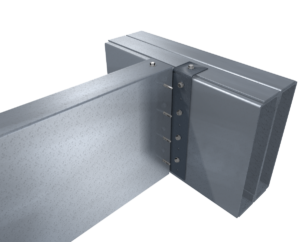
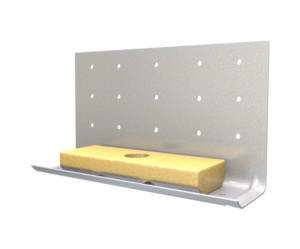
StiffClip® FS Applications
The unique design of MasterClip allows it to be installed either as a vertical deflection connection or a rigid connection. Attachment to the primary structure may be made with a PAF, screw/bolt anchors, or weld and is dependent upon the base material (steel or concrete) and the design configuration.
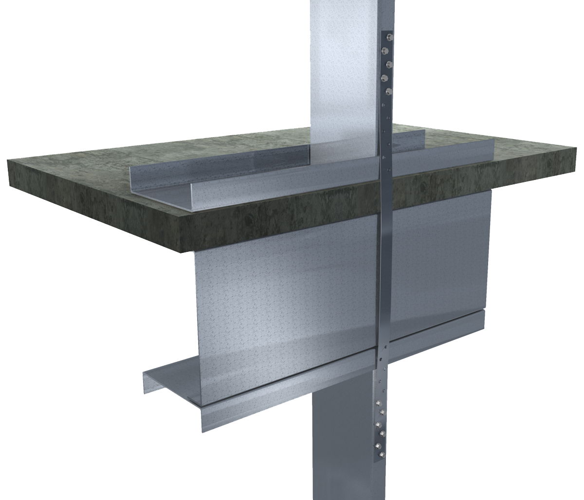
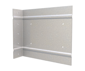
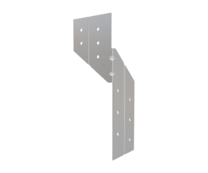
Floor Strap - Slab
Installation Instructions
- Place StiffClip FS flat against aligned wall studs.
- Attach StiffClip FS to wall studs with approved screws through guide holes
Allowable Loads
Load Table Notes
- Design loads are based on strap capacity only. StiffClip FS resists tension forces only.
- Number of fasteners used is based on fastener manufacturer’s allowable load data.
- Guide holes are located 1/2″ from each end, with 3/8″ edge distance at 2″ o.c. staggered for FS125 and 3/4″ edge distance at 2″ o.c. staggered for FS275.
- Allowable loads have not been increased for wind, seismic, or other factors.
- For LRFD strengths contact TSN technical services.
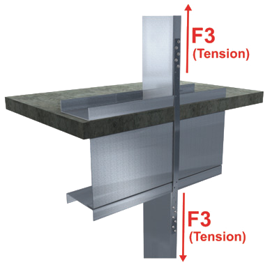
Load Direction
More Rigid Wall & Floor Connectors
Follow us on Social Media
