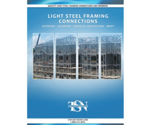
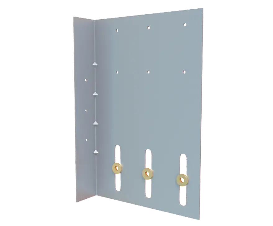
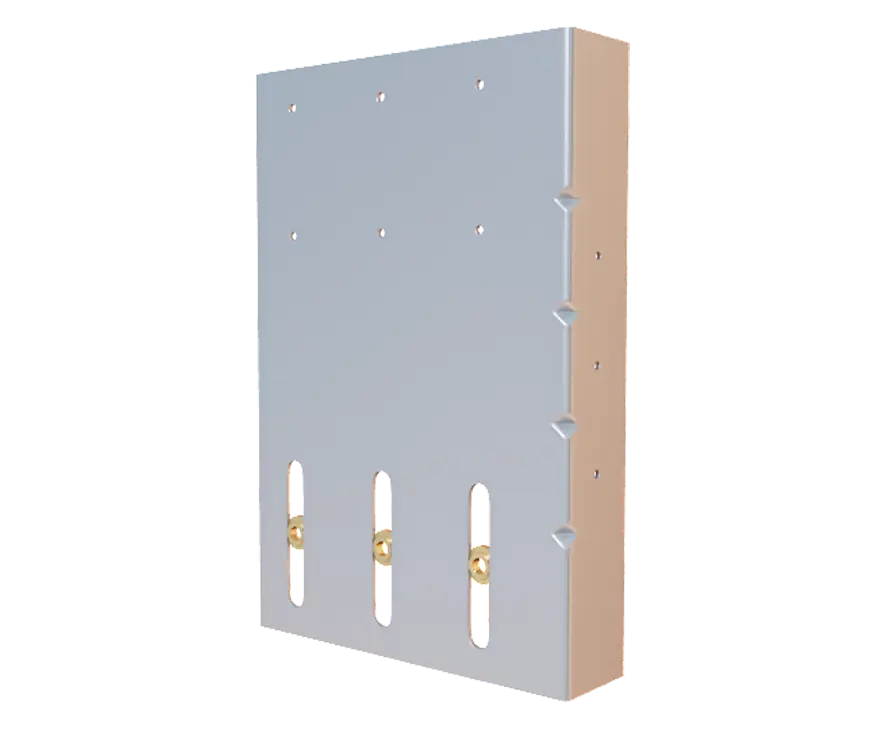
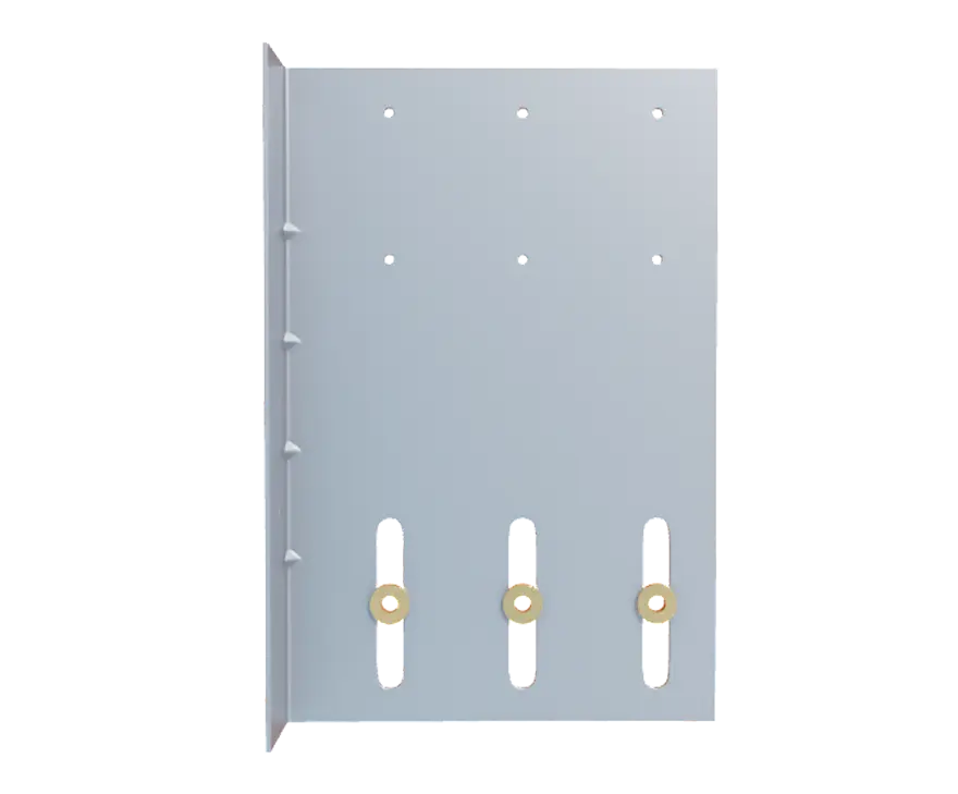
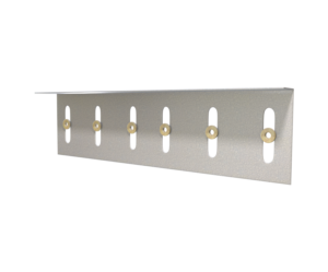
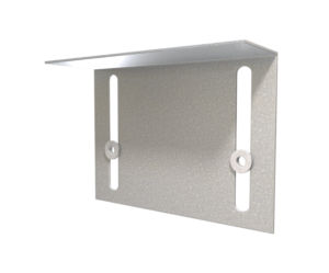
VertiClip® Splice Exterior of Slab Bypass
Features
- Load-rated positive mechanical attachment at each stud
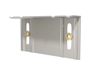
- Patented Step Bushing Technology® provides friction-free motion for smooth vertical deflection
- Load-rated #12 screws provided for vertical deflection connection to stud web
- Manufactured with certified, 68mil, 50ksi cold-formed steel
- Acts as a web stiffener
Material Composition
ASTM A1003/A1003M Structural Grade 50 (340) Type H, ST50H (ST340H): 50ksi (340MPa) minimum yield strength, 65ksi (450MPa) minimum tensile strength, 68mil minimum thickness (14 gauge, 0.0713” design thickness) with ASTM A653/A653M G90 (Z275) hot dipped galvanized coating.
Catalogs
TSN’s Product Catalogs are an essential resource for the design of cold formed steel. Developed by Engineers, the catalogs contain design data for members, connectors, and fasteners. VertiClip® Splice can be found in the following Catalogs:
|
|
|

For a full list of our product catalogs, specification sections, inspection checklists, and research reports please click here.
Blast & Seismic Design
The Steel Network is the only connector manufacturer in the US that has rated its connector products for special seismic and blast design by providing tables with LRFD design strength, nominal strength and ultimate strength for each connector.
Order Information
Nomenclature
VertiClip Splice is designated by multiplying stud depth by 100.
Example: 6″ stud
Designate: VertiClip® Splice600
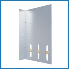
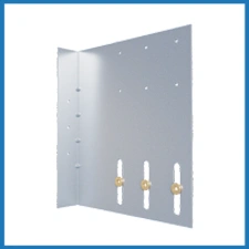
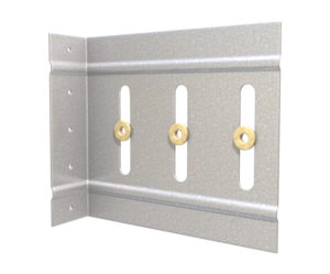
*Clip shown is a left version of VeritClip Splice. Right side versions can be made as a custom part.
VertiClip® Splice Downloads

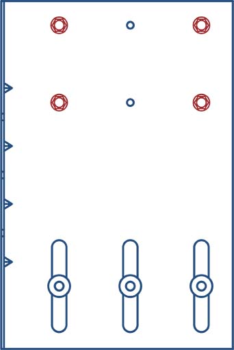
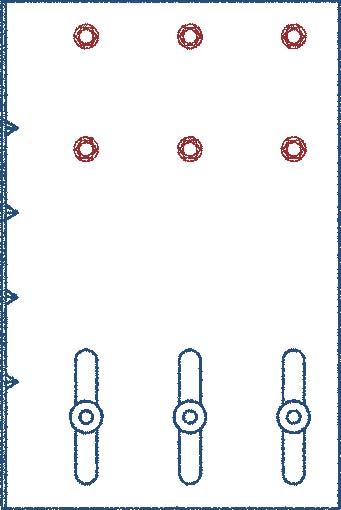
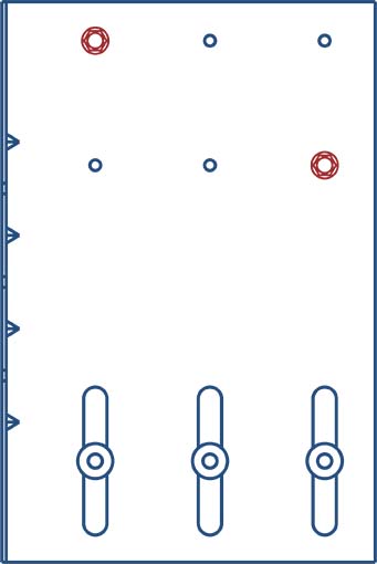
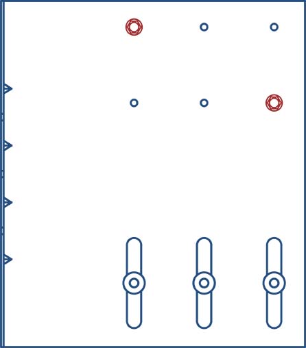
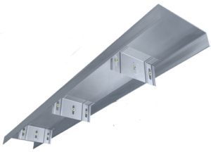
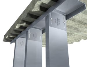
VertiClip® Splice Applications
The attachment of VertiClip to the primary structure may be made with a PAF, screw/bolt anchors or weld and is dependent upon the base material (steel or concrete) and the design configuration.
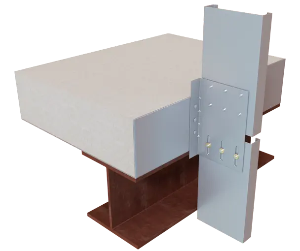
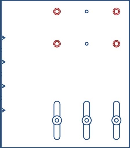
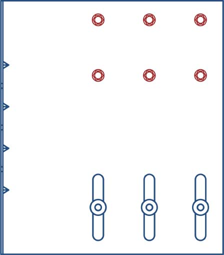
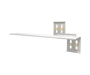
Curtain Wall Slab Bypass, Connecting 2 Studs as a Vertical Deflection Connection
VertiClip® Splice Installation Instructions
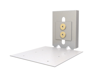
- Attach VertiClip Splice to structure with approved fasteners.
- Attach rigid stud to clip using required screws.
- Attach bottom stud to clip with provided screws through step bushings.
This Connector Features Step Bushing Technology!
Step Bushing Technology is transforming the performance of deflection clips. Designed for optimal movement and reliability, Step Bushings eliminate the need for costly, specialized shoulder screws and the tedious adjustments they require. Instead, they deliver friction-free connections that enable smooth, consistent deflection and exceptional performance.
See the Difference
Watch the video for a side-by-side comparison of a clip deflecting with Step Bushings versus a generic clip using specialized screws. Step Bushing Technology is more than an innovation—it’s a game-changer for efficiency, durability, and simplicity on the job site.
VertiClip® Splice Allowable Loads:
Load Table Notes:
- Design loads are for attachment of VertiClip Splice to stud only. Load tables reflect horizontal loads (F2) and vertical loads (F3).
- Design loads consider loads on the clip and #12 screw fasteners to the stud web.
- Loads listed reflect force in a single direction. When multiple loads react on the connection, it is the responsibility of the designer to check the interaction of forces.
- Torsional effects are considered on screw group for F3 allowable loads. It is assumed that half of the torsional moment is taken by the connection to the structure and half is taken by the connection to the stud.
- Attachment to structure engineered by others.
- Allowable loads have not been increased for wind, seismic, or other factors.
- Total vertical deflection of up to 2″ (1″ up and 1″ down). Deflection requirements greater than 1″ up and down are available.
- Fasten withn 3/4″ from the angle heel (centerline of the 1-1/2″ leg) to minimize eccentric load transfer.
- For LRFD strengths contact TSN technical services.
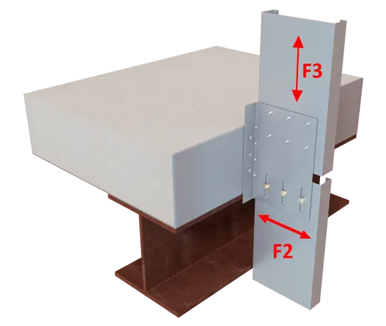
Load Directions
F2 & F3 Allowable Loads

2 screws/ 2 screws
4 screws/ 2 screws
4 screws/ 3 screws
6 screws/ 2 screws
6 screws/ 3 screws
2 screws
2 screws
6 screws
2 screws
4 screws
6 screws
More Vertical Deflection Slide Angle & Track


Follow us on Social Media
