StiffClip® CL
The StiffClip® CL series’ unique design allows for the connection of steel studs to the building’s structure by incorporating stiffened legs of a 90° angle to increase bending strength. StiffClip CL resists vertical, horizontal, and torsional loads.
Features
- Guide holes for connections to stud and deck
- Stiffeners for additional strength
- Utilizes only certified, 50ksi steel
- Reduces material (replaces heavy steel angles)
- Extensively tested
Order Information
| Designation | Qty/Box | Lbs/Box | Qty/Skid | Lbs/Skid |
| CL362/400-68 | 50 | 16 | 4,500 | 1,440 |
| CL362/400-118 | 50 | 29 | 4,500 | 2,610 |
| CL600-68 | 50 | 25 | 4,500 | 2,250 |
| CL600-118 | 50 | 41 | 2,250 | 1,980 |
| CL800-68 | 50 | 36 | 2,250 | 1,575 |
| CL800-118 | 50 | 60 | 2,250 | 2,700 |
| CL (H) Plate | 50 | 24 | 4,500 | 2,430 |
Nomenclature
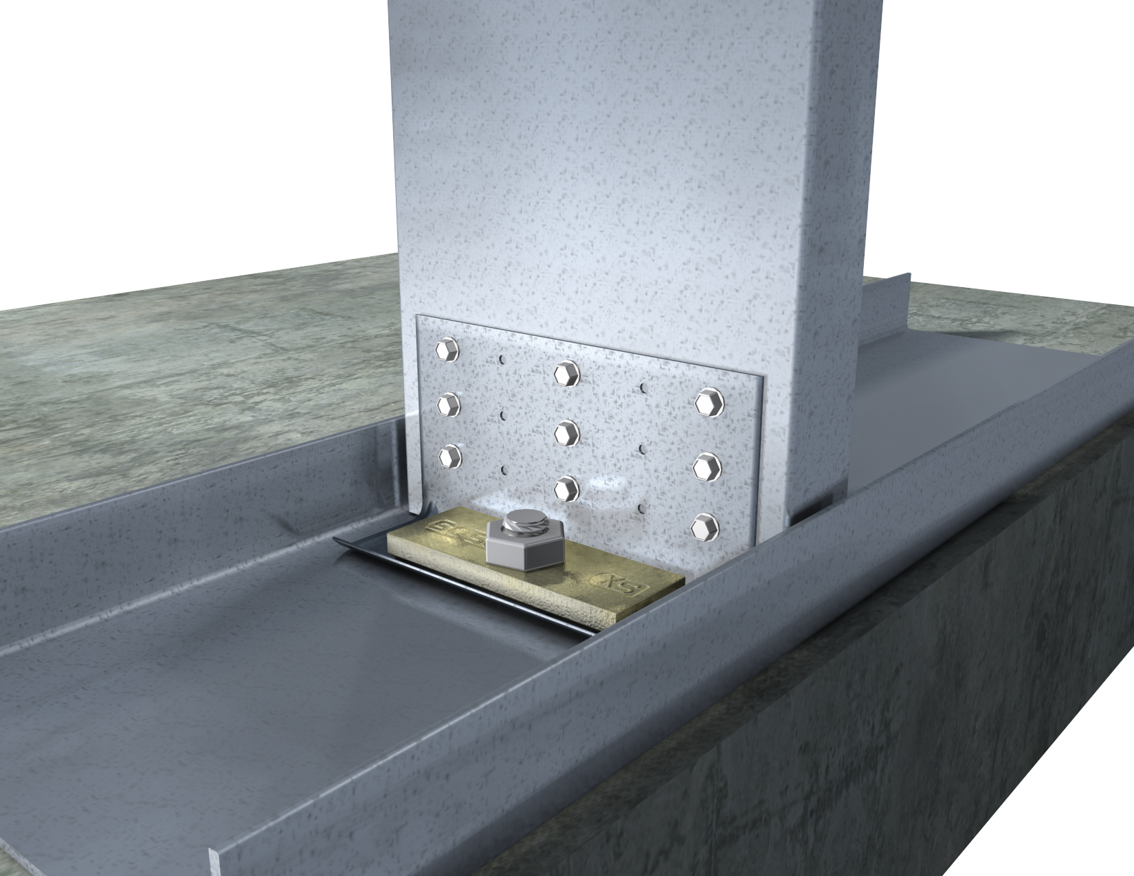
To specify Stiff Clip CL on drawings, multiply stud depth by 100, followed by the appropriate material thickness, based on strength required (see technical sheet for load tables). The Stiff Clip CL118(H) utilizes a plate in the 1½” leg (shown in application image).
Example: 6” stud, uplift load of 650lbs.
Designate: StiffClip® CL600-68.
Material Composition
68mil: ASTM A1003/A1003M Structural Grade 50 (340) Type H, ST50H (ST340H): 50ksi (340MPa) minimum yield strength, 65ksi (450MPa) minimum tensile strength, 68mil minimum thickness (14 gauge, 0.0713” design thickness) with ASTM A653/A653M G90 (Z275) hot dipped galvanized coating.
118mil: ASTM A1003/A1003M Structural Grade 50 (340) Type H, ST50H (ST340H): 50ksi (340MPa) minimum yield strength, 65ksi (450MPa) minimum tensile strength, 118mil minimum thickness (10 gauge, 0.1242” design thickness) with ASTM A653/A653M G90 (Z275) hot dipped galvanized coating.
“H” Plate: ½” steel, ASTM A36, 36ksi min yield, 58-80ksi min tensile, with ASTM B633 Type II Yellow Zinc Coating, or Paint, or Equivalent.
Catalogs

|
|
For a full list of our product catalogs, specification sections, inspection checklists, and research reports please click here.


US Patents #7,533,508
StiffClip® CL Downloads

StiffClip® CL Applications
The attachment of StiffClip CL to the primary structure may be made with a PAF, screw/bolt anchors or weld and is dependent upon the base material (steel or concrete) and the design configuration.
Anchor
Installation Instructions
- Place StiffClip® CL at bottom of stud.
- Attach clip to deck with approved anchor.
- Secure clip to stud with required amount of symmetrically placed #12 screw fasteners.
- If the (H) Piece is used, secure to clip with approved anchor to deck.
Allowable Loads
 Pattern 1: 4 ScrewsPattern 1: 4 ScrewsPattern 1: 4 ScrewsPattern 1: 4 ScrewsPattern 1: 4 Screws
 Pattern 1: 4 ScrewsPattern 1: 4 ScrewsPattern 1: 4 ScrewsPattern 1: 4 ScrewsPattern 1: 4 Screws
 Pattern 2: 9 ScrewsPattern 2: 9 ScrewsPattern 2: 9 ScrewsPattern 2: 9 ScrewsPattern 2: 9 Screws
 Pattern 3: 6 ScrewsPattern 3: 6 ScrewsPattern 3: 6 ScrewsPattern 3: 6 ScrewsPattern 3: 6 Screws
 Pattern 3: 6 ScrewsPattern 3: 6 ScrewsPattern 3: 6 ScrewsPattern 3: 6 ScrewsPattern 3: 6 Screws
 Pattern 4: 10 ScrewsPattern 4: 10 ScrewsPattern 4: 10 ScrewsPattern 4: 10 ScrewsPattern 4: 10 Screws
 Pattern 5: 6 ScrewsPattern 5: 6 ScrewsPattern 5: 6 ScrewsPattern 5: 6 ScrewsPattern 5: 6 Screws
 Pattern 5: 6 ScrewsPattern 5: 6 ScrewsPattern 5: 6 ScrewsPattern 5: 6 ScrewsPattern 5: 6 Screws
 Pattern 6: 10 ScrewsPattern 6: 10 ScrewsPattern 6: 10 ScrewsPattern 6: 10 ScrewsPattern 6: 10 Screws
Load Table Notes:
- Design loads are for attachment of StiffClip CL to stud only. Load tables reflect in plane of wall loads (F1), horizontal loads (F2), vertical loads (F3), and overturning loads (M1).
- M1 loads are reported as Max. Load divided by a Factor of Safety. M1 loads may be limited by the Serviceability Load calculated as Clip Stiffness times the Serviceability Limit in radian.
- Stiffness is the Allowable Clip Moment divided by the clip rotation measured at half of the Max Allowable Clip Moment.
- Design loads consider loads on the clip and #12 screw fasteners to the stud web.
- Loads listed reflect force in a single direction. When multiple loads react on the connection, it is the responsibility of the designer to check the interaction of forces.
- Torsional effects are considered on screw group for F2 allowable loads. It is assumed that half of the torsional moment is taken by the connection to the structure and half is taken by the connection to the stud.
- Attachment to structure engineered by others.
- Allowable loads have not been increased for wind, seismic, or other factors.
- Allowable load tables incorporate eccentric loading of fasteners. Values with a welded connection may increase.
- Guide holes are in place for fastener installation efficiency. All guide holes may not require fasteners. Fastener amount determined by the designer. Screw fastener should be symmmetrically placed in guide holes. Refer to screw pattern diagrams below for placement.
- Fasten within 3/4″ from the angle heel (centerline of the 1-1/2″ leg) to minimize eccentric load transfer.
- Center guide hole is 9/16″ in diameter for 1/2″ anchors. Middle guide holes are 5/16″ in diameter for 3/8″ anchors. Outer guide holes and guide holes in 3″ leg are 0.141″ in diameter.
- For LRFD strengths contact TSN technical services.

Load Direction

Anchor Bolt Design
Anchor Bolt Design Equation

Screw Patterns
Follow us on Social Media
