If you wanted to build with cold-formed steel (CFS) framing, how high could you go?
While some say 10 stories is the limit for CFS, what could a structural engineer do if he thought “outside the box”?
The Steel Framing Industry Association (SFIA) decided to find out. The Association commissioned Patrick Ford, P.E., principal at Matsen Ford Design in Waukesha, Wisconsin, and technical director at SFIA, to create a CFS-framed high-rise. In April 2016, at an American Iron and Steel Institute meeting, Ford unveiled the SFIA Matsen Tower, a 40-story residence named after his late partner, John P. Matsen.
The SFIA Matsen Tower has opened the door to a new way of incorporating CFS framing into high-rise buildings.
“It’s time for structural engineers and our future engineers in school to see what can be done,” said Larry Williams, Executive Director at SFIA. “CFS can rise much higher than was ever thought possible and taller than any wood structure ever conceived.”
2.5 billion new urban dwellers
Is there a need to go skyward? Increasingly, the answer is yes.
According to the United Nations (UN), the world’s urban population grew rapidly from 746 million in 1950 to 3.9 billion in 2014. Today, 54 percent of the world’s population lives in cities, and that’s expected to jump to 66 percent by 2050, when an additional 2.5 billion people will need urban housing.
Since urban space is limited, building owners in the future will meet demand by going vertical. And the more ways to go vertical, the better.
Not all architects, engineers, and contractors are aware of CFS framing’s high strength and ductility. Some may think of CFS as a light-gauge material only suitable for interior drywall partition framing and a framing backup for a variety of exterior building finishes.
Is CFS suitable for load-bearing support of a 40-story building? Yes. CFS’s gravity and lateral-resisting properties make it perfect as the load-bearing material for mid-rise structures. While 10 stories is the current perceived height limit for CFS C-studs and joists, the SFIA Matsen Tower proves otherwise.
“While several very good technical review issues [of the tower] have been brought forth, we could formalize the design for construction,” Ford explained.
Design uses common CFS profiles and thicknesses
The SFIA Matsen Tower is a residential R3 apartment building.

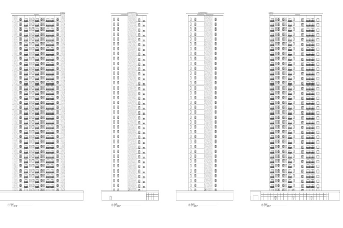
Elevations showing wider front and rear wall openings and narrower bearing wall openings on the building’s sides.
Its design was restricted to CFS studs, joists, and other members to what’s commonly used in CFS load-bearing construction. Spacings were limited to the industry-typical 12”, 16”, and 24” on centers. Double studs were allowed, but only for the repetitive members of the system. The SFIA Matsen Tower is designed to use common CFS profiles and thicknesses, and would not require the development of any specialized CFS framing products.
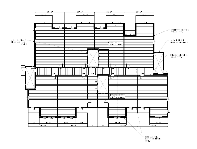
The other ground rules applied to the tower: 10’-0” story heights and 25’-6” center-to-center demising wall spacings, which create roughly 25’ clear spans.
How can the SFIA Matsen Tower rise 40 stories primarily on CFS structural framing?
The materials list includes lightweight EPDM on metal deck roof, lightweight 1-1/2” gypsum concrete on structural 0.6 C deck floor, lightweight exterior wall finishes of architectural metal, EIFS, or finished exterior cement board panels.
Here are some details:
- Typical floor assembly: LWGC on 0.6 C deck on C joists with RC and a GWB ceiling.
- Corridor walls: These are also bearing walls, supporting the shallower corridor framing.
- Exterior walls: CFS studs, GWB and sheathing with rigid insulation and architectural metal panel, EIFS or cement panel. The front and rear walls are non-bearing, aside from their self-weight and the balconies.
- Aluminum balconies: They’re wing-wall supported and are provided for each unit. But, they can also be bracketed to double studs or corner posts in the exterior walls.
- Vision areas: Openings are provided in the front and rear, with smaller openings in the end unit bearing walls. The openings are limited to 4’-0” widths in the bearing walls, 6’-0” widths in the typical exterior walls.
Strength factor: Repetitive C studs
What makes the 40-story tower so solid? Structurally, it features repetitive C studs and joists for the primary gravity load-carrying frame.
The major CFS exception is the MWFR primary bracing. This is provided by reinforced, cast-in-place concrete shear cores at the elevators and stairs.

Reinforced, cast-in-place concrete shear cores at the elevators and stairs must be high strength (7,000 psi) concrete and range in thickness from 8” at the top stories to 20” at the bottom.
The tower is designed to withstand wind speed gusts as high as 115 mph.
“This could be built in the vast majority of the United States,” Ford said. “Hurricane coastal areas could be an issue. High seismic might be an issue, but I don’t think so.”
The C studs are designed for a worst case scenario of wind load and eccentric axial loads from the joists. The deflection criteria includes an L/360 limit for the wall members, and L/480 at live load for the floor members.

Stud assemblies are designed for the worst case combination of uniform lateral and eccentric live and total load from the joists.
Stud spacing and prefabrication
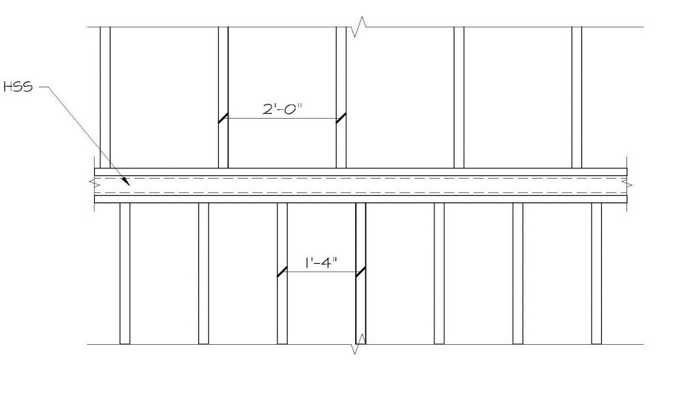
If the SFIA Matsen Tower were built, two elements would be critical: The first involves the spacing of CFS studs. Load would be distributed from bearing studs above to studs at different spacing below.

The stud offsets at spacing changes are identical throughout.
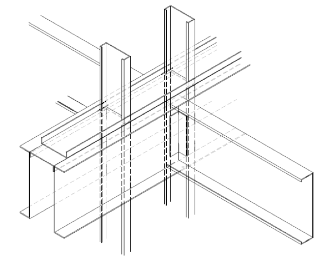
These stud offsets would occur in essentially two locations. One is from 24”o.c. to 16”o.c members at the 34th story. The other is at the reduction from 16” to 12”o.c. at the 30th story. More robust tube elements — HSS 6”x 3 x 1/4” and HSS 6 x 4 x 5/16” continuous, respectively — with top and bottom plates are required.
The tower’s second critical requirement would be to prefabricate the walls. The building would need true full seating of stud to track, and compressed web to web in a fixture, prior to the wall frame being welded. Welded connections are strongly recommended.
Bridging forces would accumulate in the walls. But these forces would be taken up by intersecting and reverse-orienting the CFS members and by corner members. Occasional tee braces can be used, but they would be required only at the very upper levels.
Even with axial forces of over 60 kips per member, double studs would work completely unbraced at lower levels.
48-story CFS structural framing
In the end, the SFIA Matsen Tower is a conservative design. Few load reductions were used in calculating the requirements of the CFS members. For example, wind load weighs heavily into the moment of each CFS stud. But, wind load was not reduced as it could be, which would allow for more framing economies.
Also, the live load reductions for the walls were based only on the incoming tributary load area from each joist at the wall member. With the tributary area calculated per supporting member as one third of the incoming span, and the wall as a discrete bearing element — an entirely acceptable methodology in some circles — the height of the SFIA Matsen Tower becomes 48 stories.
Will building owners clamor to erect 40-story CFS-framed structures? Maybe in the future, if the design proves to be economical.
“We make no claim that this is the most efficient way to do a 40-story tower,” Ford said.
Still, the SFIA Matsen Tower shows how CFS’s strength benefits are much greater than many architects, engineers, and contractors may realize.
According to Ford, “Cold-formed steel has far greater capacity than it’s being used for.”
Article cited by BuildSteel.org
