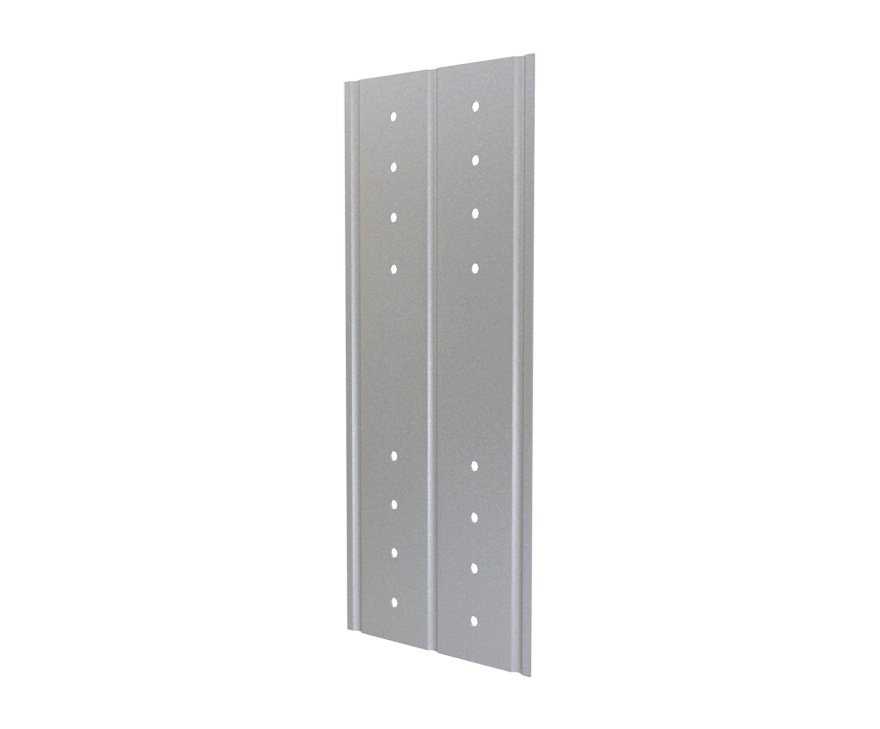
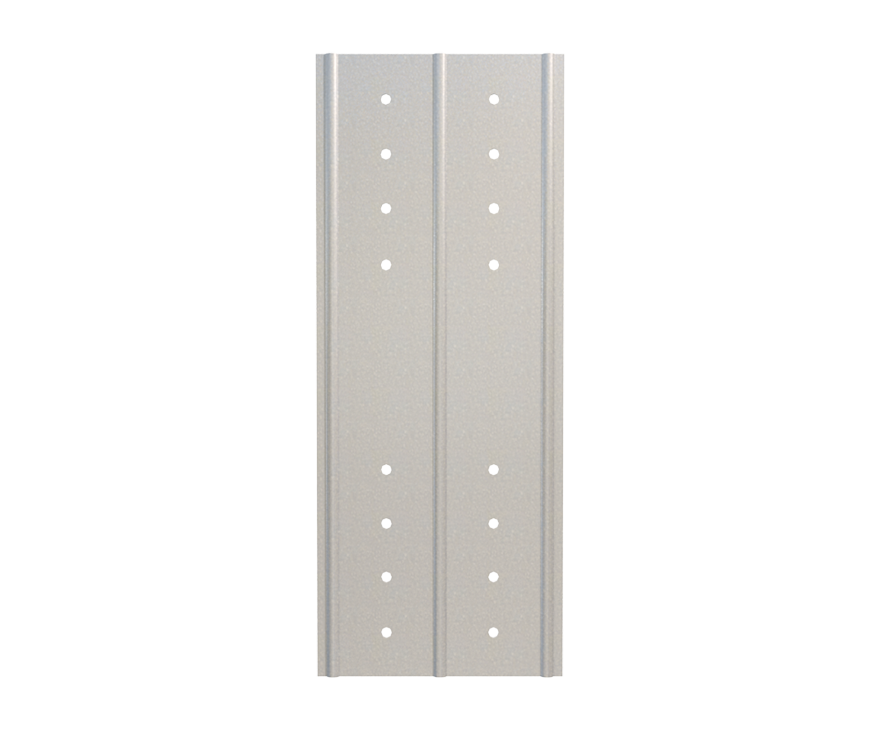
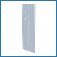
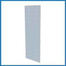
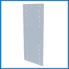
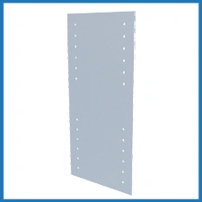
StiffClip® WC
Features
- Stiffened ribs for added strength (use varies with each clip)
- Guide holes for attachment to framing members (0.172” dia.)
- No time and expense spent cutting steel shapes
- Structurally load tested
- Meets all building code criteria
Material Composition
54mil: ASTM A1003/A1003M Structural Grade 40 (275) Type H, ST40H (ST275H): 40ksi (275MPa) minimum yield strength, 55ksi (380MPa) minimum tensile strength, 54mil minimum thickness (16 gauge, 0.0566″ design thickness) with ASTM A653/A653M G90 (Z275) hot dipped galvanized coating.
118mil: ASTM A1003/A1003M Structural Grade 50 (340) Type H, ST50H (ST340H): 50ksi (340MPa) minimum yield strength, 65ksi (450MPa) minimum tensile strength, 118mil minimum thickness (10 gauge, 0.1242″ design thickness) with ASTM A653/A653M G90 (Z275) hot dipped galvanized coating.
Catalogs
TSN’s Product Catalogs are an essential resource for the design of cold formed steel. Developed by Engineers, the catalogs contain design data for members, connectors, and fasteners. StiffClip® WC can be found in the following Catalogs:
For a full list of our product catalogs, specification sections, inspection checklists, and research reports please click here.
Order Information
Nomeclature
StiffClip WC is designated by multiplying stud depth in inches by 100, then listing material, thickness and length.
Example: 3½” stud depth, 54mil steel thickness, 10″ long
Designate: StiffClip® WC350-54 10″
StiffClip® WC Downloads
StiffClip® WC Applications
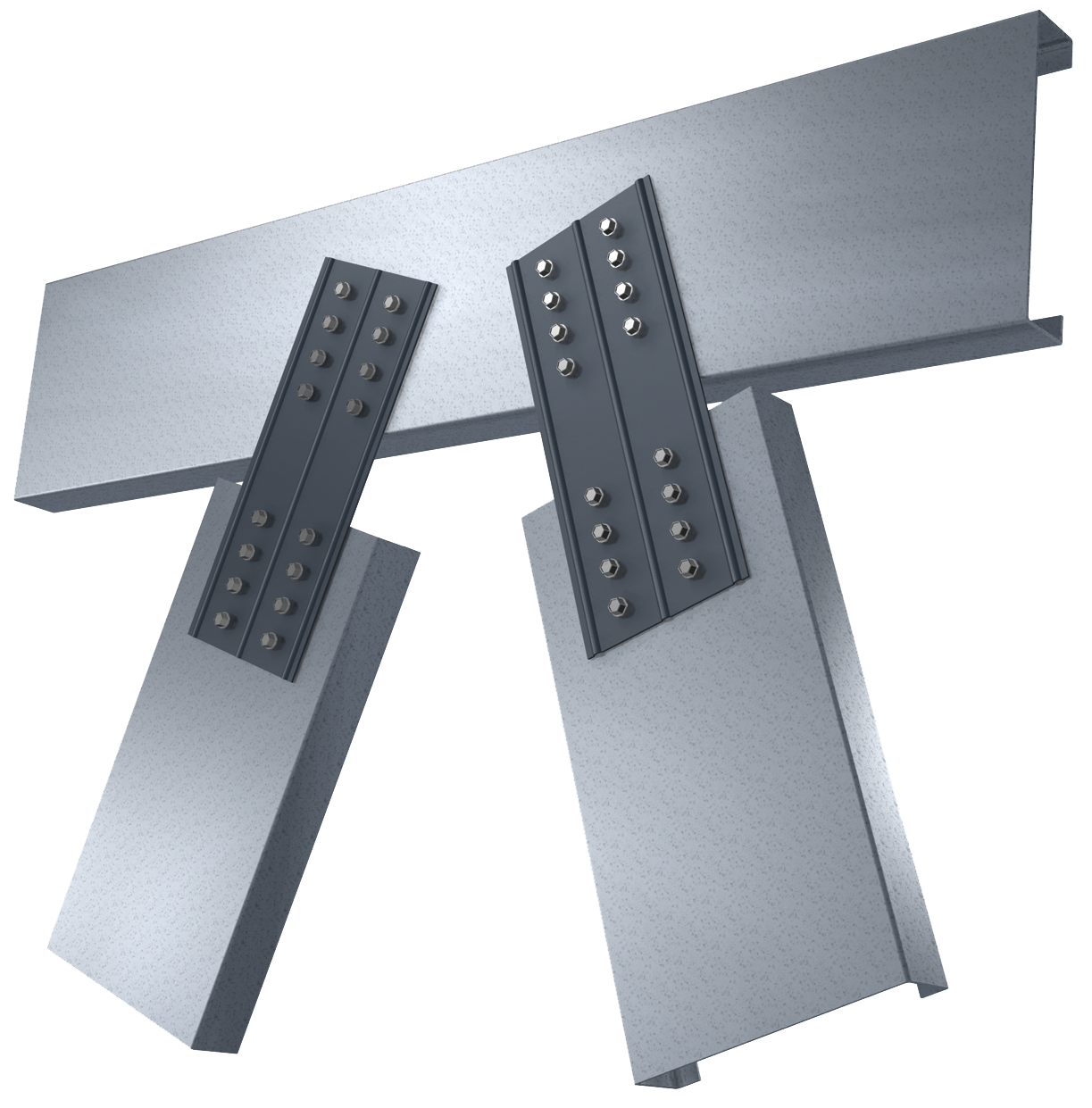
Installation Instructions
- Place StiffClip WC at web of each framing member.
- Attach StiffClip WC to framing member with required screws through guide holes
Allowable Loads
Load Table Notes:
- Design loads are for attachment of StiffClip WC to light gauge framing members only. Allowable load tables apply to tension and compression on StiffClip WC utilizing the fastener patterns shown on the next page.
- All guide holes may not require fasteners. Number and size of fasteners used is based on fastener manufacturer’s allowable load data, and is to be verified by the designer.
- Allowable loads have not been increased for wind, seismic, or other factors.
- For LRFD strengths contact TSN technical services.
* Maximum allowable load is based on structural testing.
** Maximum allowable load is based on calculations.
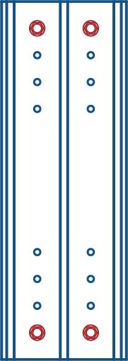
2 Screws
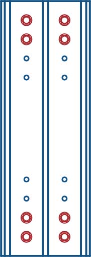
4 Screws
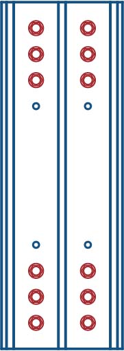
6 Screws
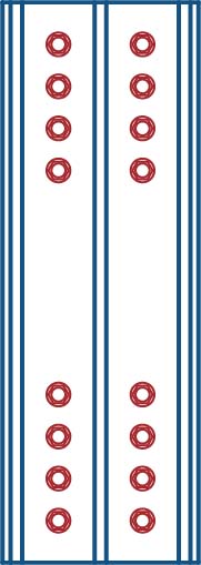
8 Screws
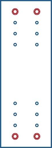
2 Screws
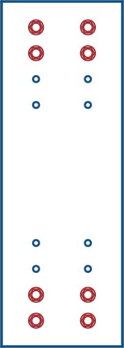
4 Screws
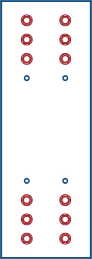
6 Screws
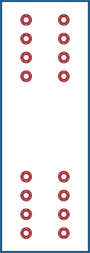
8 Screws
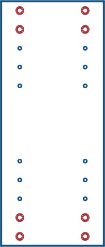
4 Screws
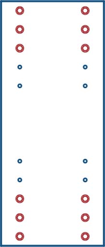
6 Screws
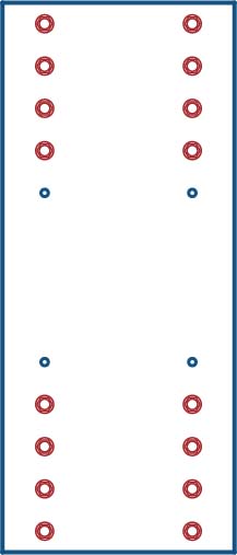
8 Screws
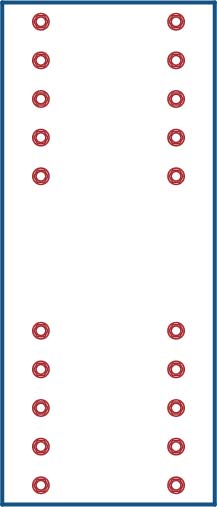
10 Screws
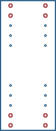
4 Screws
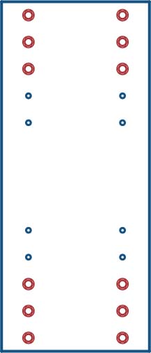
6 Screws
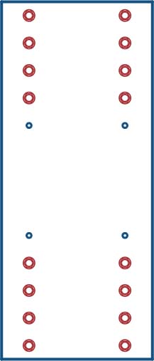
8 Screws
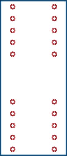
10 Screws
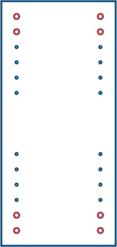
4 Screws
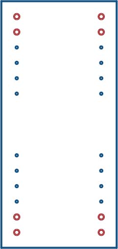
6 Screws
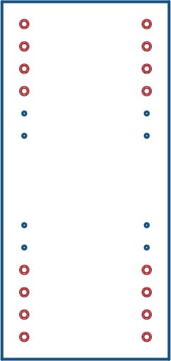
8 Screws
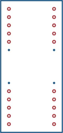
10 Screws
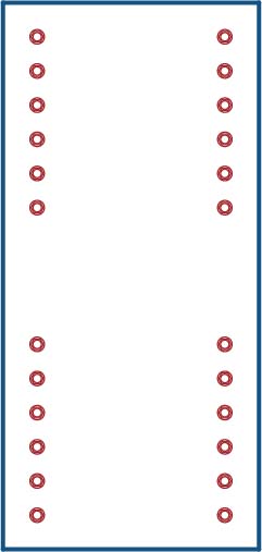
12 Screws
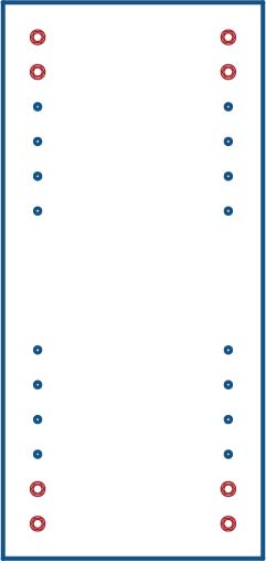
4 Screws
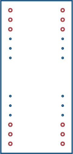
6 Screws
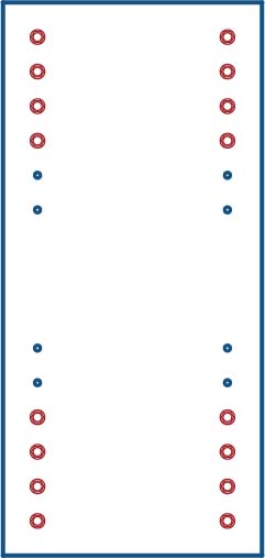
8 Screws
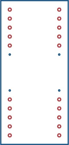
10 Screws
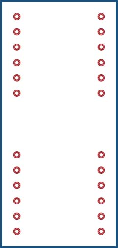
12 Screws
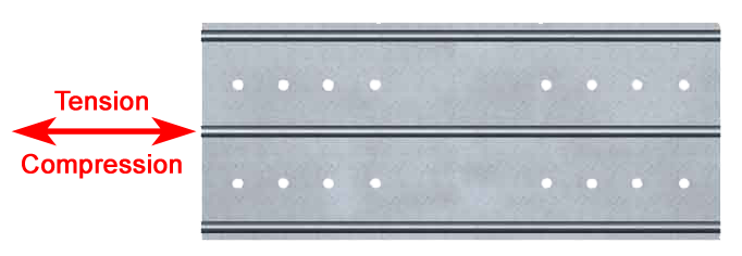
Load Direction
Follow us on Social Media

