Cold-formed steel (CFS) framing has a proven track record of providing energy-saving and sustainability benefits for buildings of all shapes and sizes. CFS framing can also be the primary structural element in mid-rise construction and meet the exterior continuous insulation requirements set by IECC, ASHRAE 90.1, ASHRAE 189.1, IgCC and LEED.
Robert Grupe, director of technical services at the Association of the Wall and Ceiling Industry, says 5 CFS framing details are basic to any mid-rise building. Grupe presented these details in a recent SFIA webinar entitled, Cold-Formed Steel Framing in Mid-Rise Construction. Developed jointly by AWCI and the Steel Framing Industry Association (SFIA), these 5 details have been peer reviewed and are featured in industry training programs:
1. CFS and the Roof Parapet
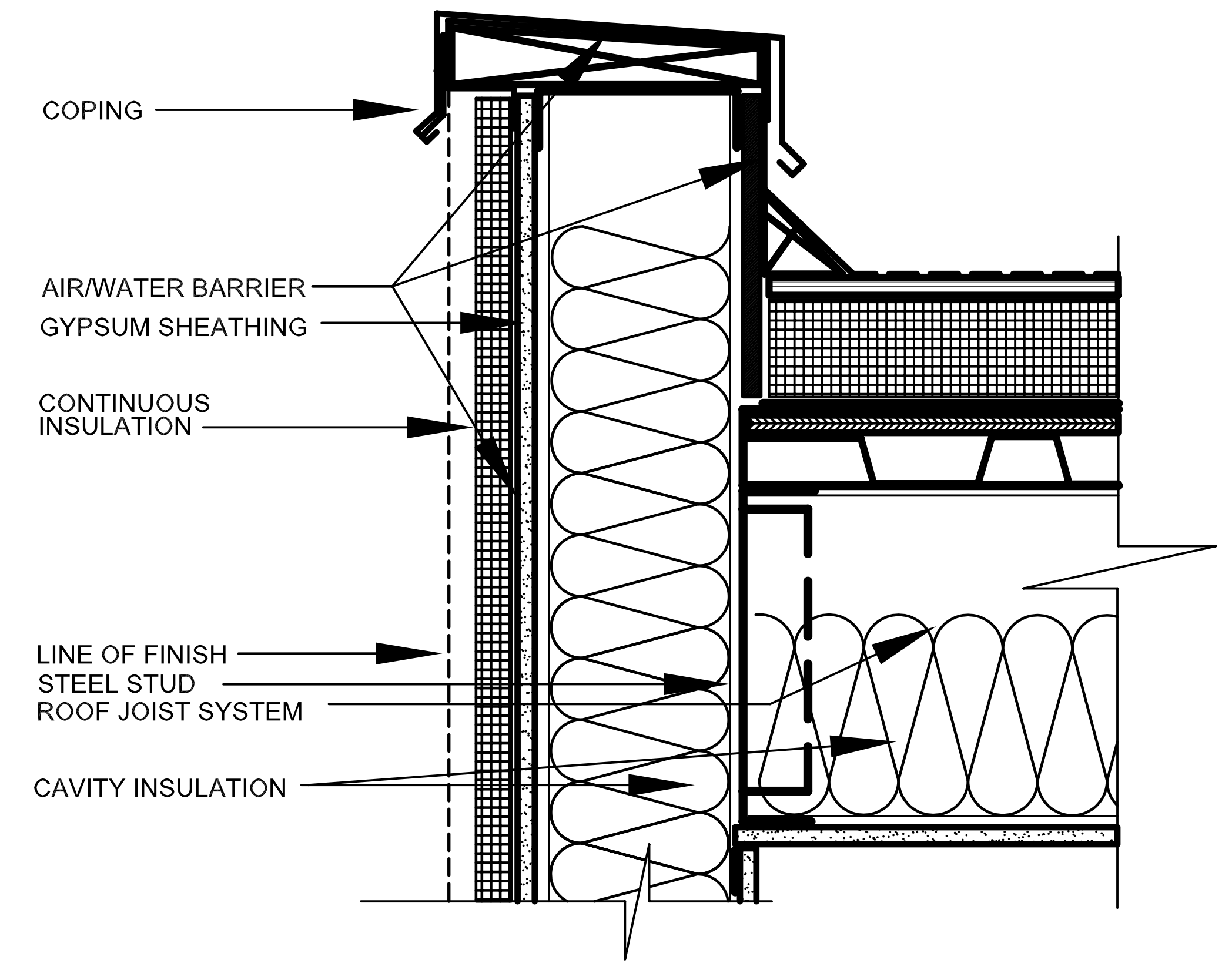
Source: AWCI Technology Center, Roof Parapet Detail – Any Finish.
Key Points
- CFS roof joist attached to C-shaped roof track
- Roof track attached to inside flange of continuous CFS stud
- Air/water resistive barrier is continuous for steel deck over roof parapet (under the roof coping) and over the face of the water-sensitive sheathing
- Stud cavity filled with insulation (R-13)
- Continuous insulation thickness as required by IECC
2. CFS and the Window Head

Source: AWCI Technology Center, Window Head Detail – Any Finish.
Key Points
- Vertical CFS studs are supported by boxed header made up of two CFS studs size as required
- Insulation removed from header section for clarity of framing
- Retain continuity of WRB onto flashing with special transition materials
- Another transition membrane is used to cover water-sensitive sheathing core and runs onto CFS track that makes up the bottom portion of the boxed header
- Stud cavity filled with insulation (R-13)
- Continuous insulation thickness as required by IECC
3. CFS and the Window Jamb

Source: AWCI Technology Center, Window Jamb Detail – Any Finish.
Key Points
- Vertical CFS Jamb Studs are shown here as two studs face-to-face. Sized to carry addition gravity load as required
- Insulation removed from jamb section for clarity of framing
- Retain continuity of WRB onto web of jamb studs with special transition materials
- Stud cavity filled with insulation (R-13)
- Continuous insulation thickness as required by IECC
4. CFS and a Balloon Framed Exterior Wall
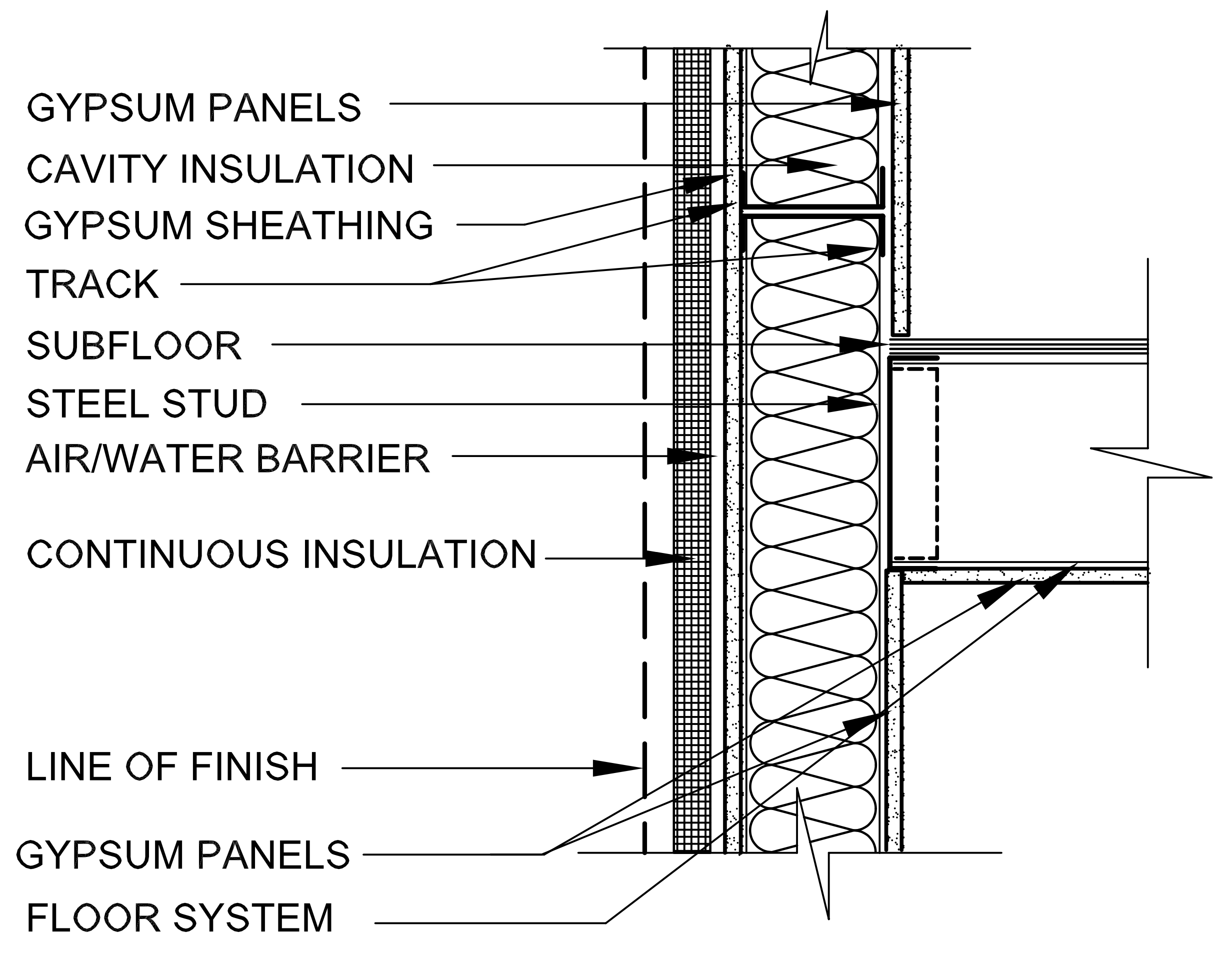
Source: AWCI Technology Center, Balloon Framed Intermediate Floor Detail – Any Finish.
Key Points
- CFS floor joist attached to C-shaped floor track
- Floor roof track attached to inside flange of continuous CFS stud
- Vertical wall framing broken just above top plane of floor
- Retain continuity of WRB
- Stud cavity filled with insulation (R-13)
- Continuous insulation thickness as required by IECC
5. CFS and the Foundation
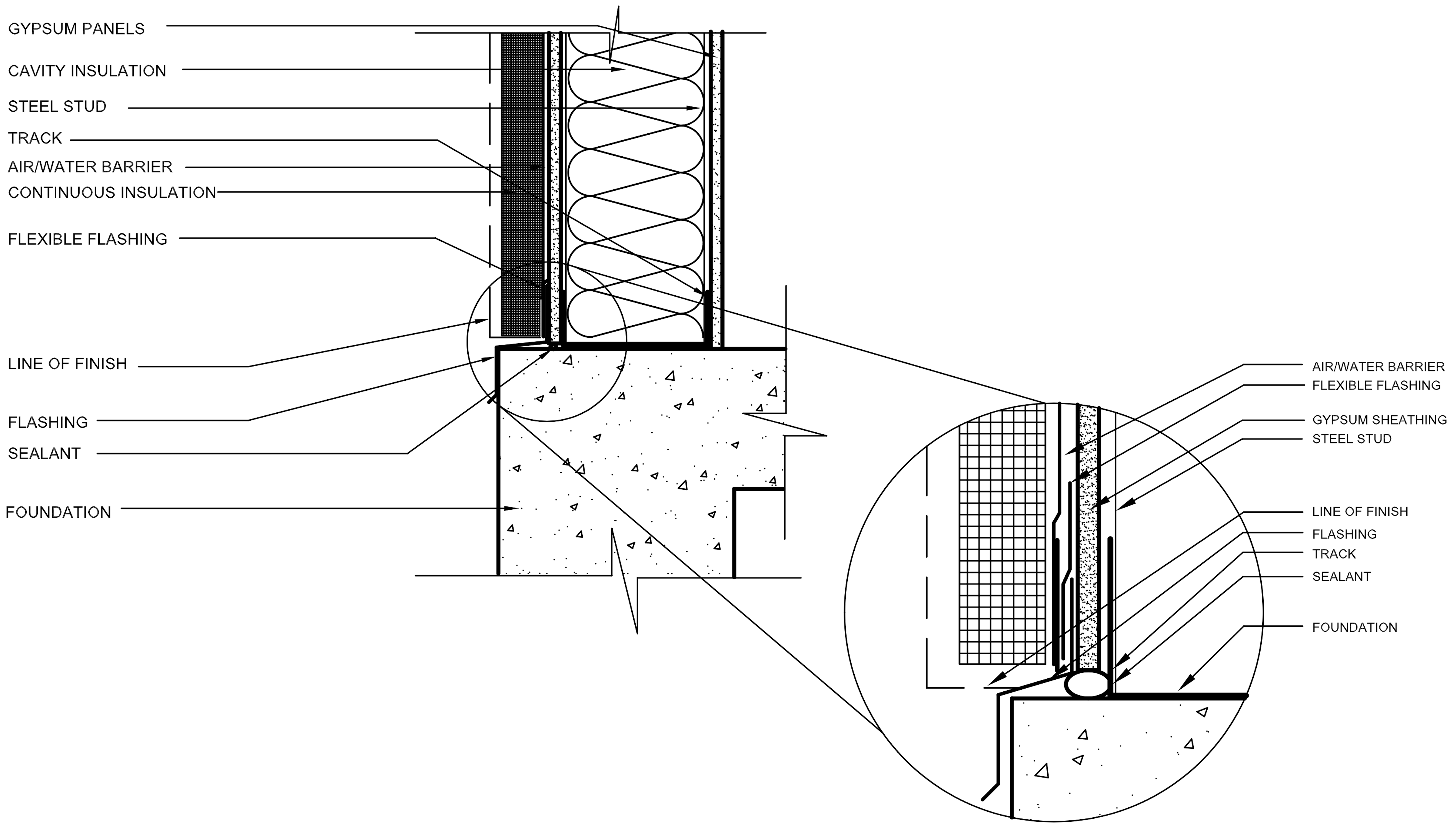
Source: AWCI Technology Center, Foundation Detail – Any Finish.
Key Points
- CFS vertical stud attached to C-shaped floor track
- Floor roof track attached to top of concrete
- Required foundation insulation (per IECC) removed to clarify framing
- Retain continuity of WRB onto flashing with special transition materials
- Bead of sealant at bottom of water sensitive sheathing and on top of concrete slab
- Stud cavity filled with insulation (R-13)
- Continuous insulation thickness as required by IECC
Lateral Bracing
One detail that is not provided within the drawings is lateral bracing. As load is placed on a CFS stud, it has a tendency to rotate around its shear center due to its asymmetrical shape. Therefore, the stud must be stabilized with lateral bracings — U-shaped channels, 16 gauge or 54 mils, that run through the punch-outs and are spaced vertically on the walls.
Article cited from BuildSteel.org