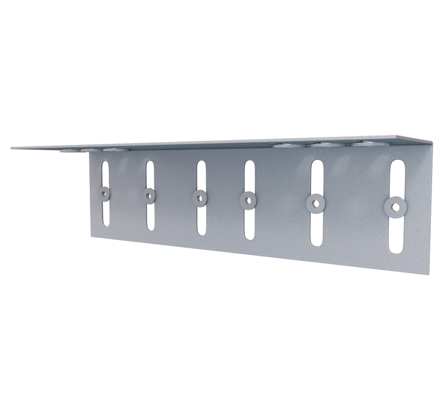
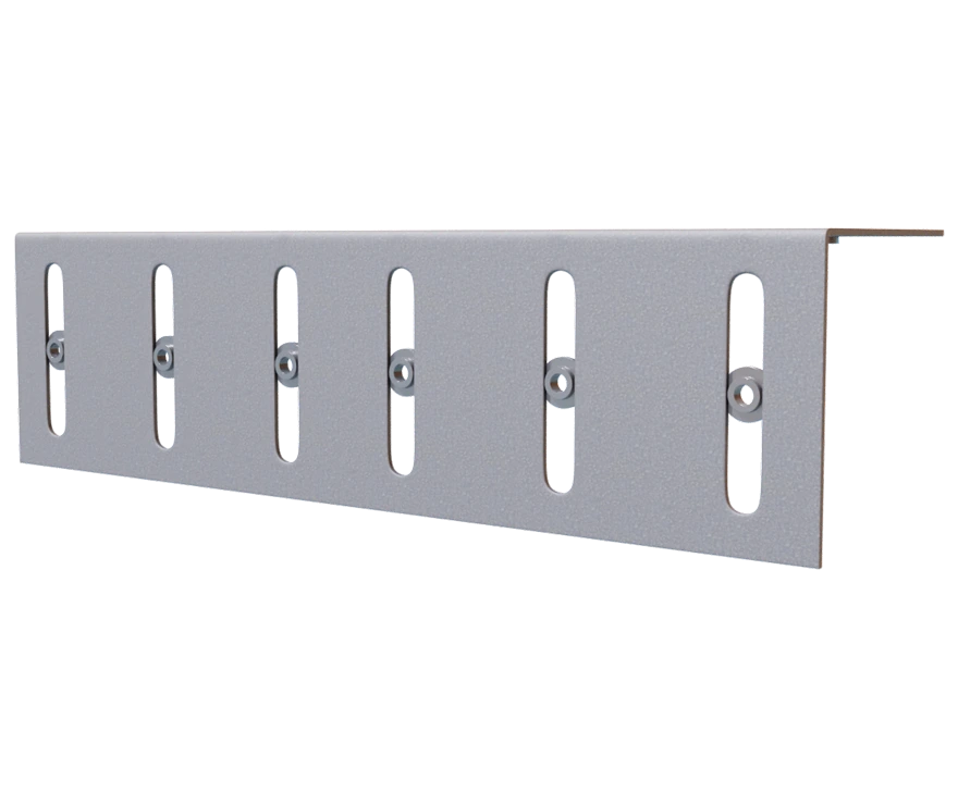
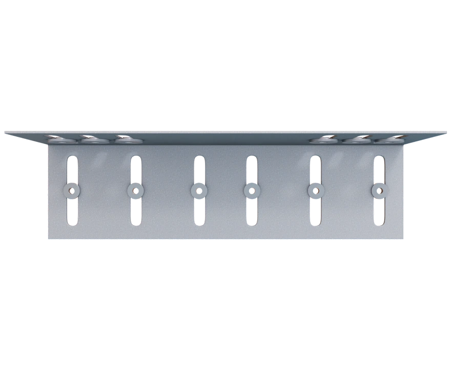
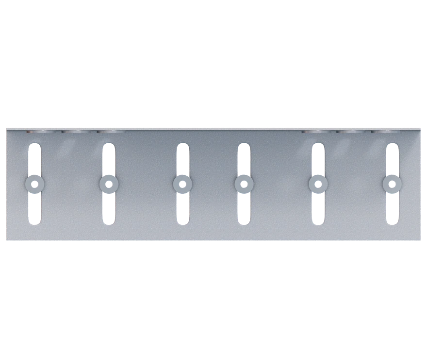
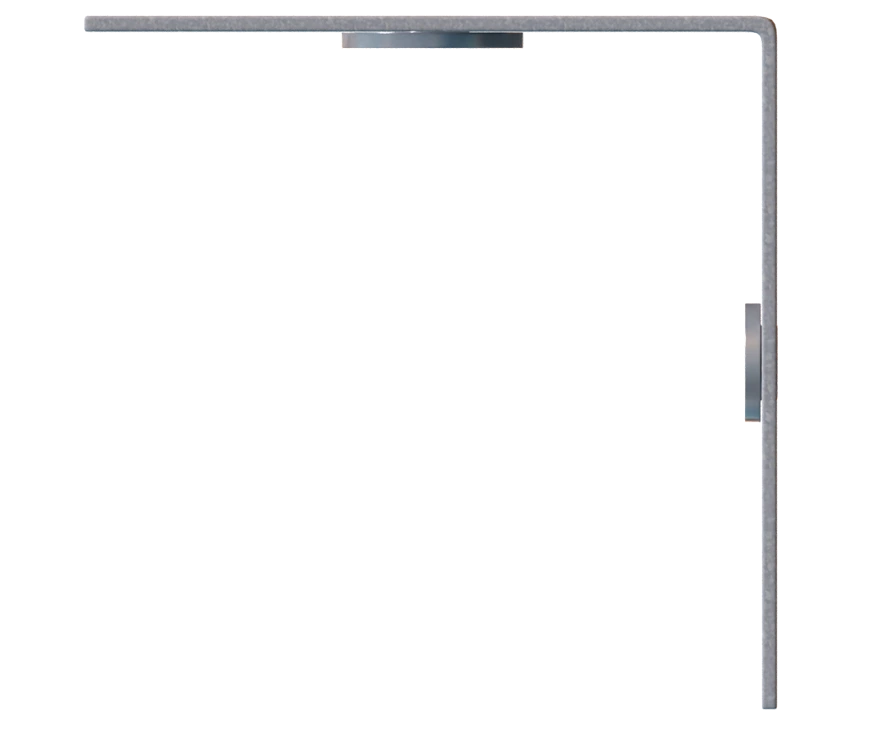
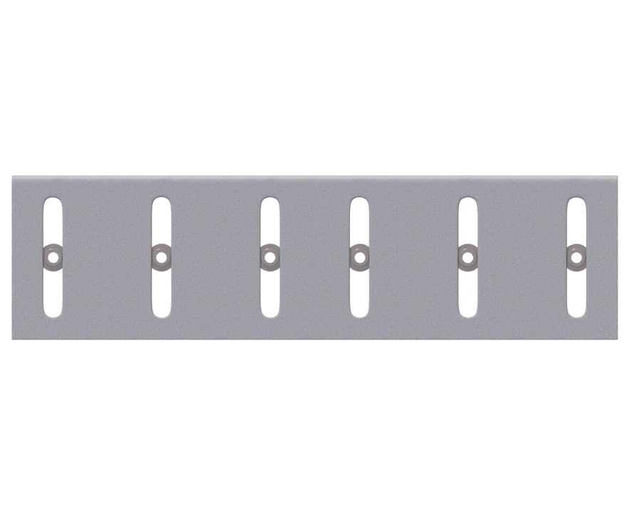
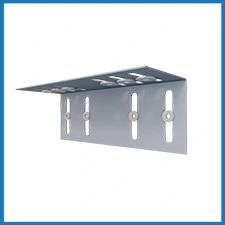
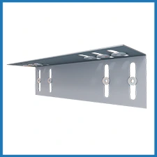
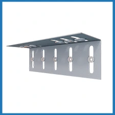
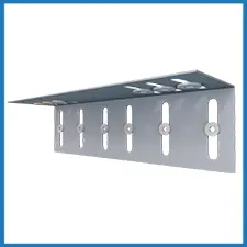
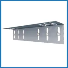
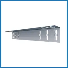
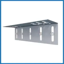
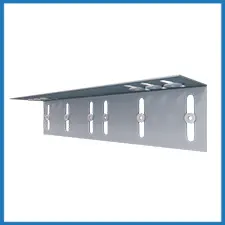
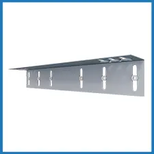
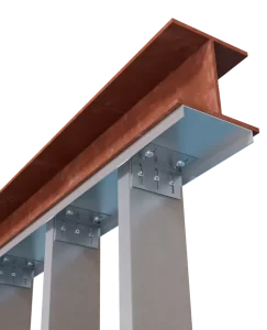
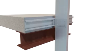
DriftClip® DSLS Exterior Bypass Strut
This drift slide angle strut is used to connect exterior cold-formed steel curtain wall studs to structural steel frame when large stand-off conditions exist, bypassing the primary structure, while allowing for up to 2” vertical deflection (1” up and down) and 2” lateral drift (1” left and right-in-plane). TSN’s patented Step Bushing Technology® provides an anti-friction and anti-seizure connection between the clip and both the stud web surface & track.
Features
- ICC-ES Approved, report #ESR-2049
- If more than 2” lateral drift is required, contact TSN engineering for a custom solution
- Load-rated positive mechanical attachment at each stud
- Patented Step Bushing Technology provides friction-free motion for smooth vertical deflection
- Eliminates loose friction-held assemblies, heavy deep-leg track, & top row of wall bridging/strapping
- Load-rated #12 screws provided for vertical deflection connection to stud web
- Manufactured with certified, 50ksi, 97mil, G90 cold-formed steel
Material Composition
Catalogs
TSN’s Product Catalogs are an essential resource for the design of cold formed steel. Developed by Engineers, the catalogs contain design data for members, connectors, and fasteners. DriftClip® DSLS can be found in the following Catalogs:
|
|
|


For a full list of our product catalogs, specification sections, inspection checklists, and research reports please click here.
US Patents #6,612,087
Order Information
Nomenclature
DriftClip DSLS is designated by stud depth and clip length required. Clip length includes a minimum of 3″ for steel (5.5” for concrete) of clip material for attachment to structured added to stud depth, plus the distance of the stud from the structure. *
Example: 6″ stud, 6″ tolerance, 3″ to steel structure
Designate: DriftClip® DSLS600-15
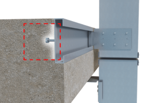
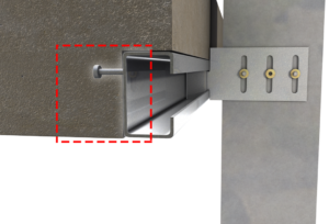
* Parts with the designation “-CA” on the end of the part name include special bushings to allow connection to the underside of a concrete slab using two 1/4″ concrete screw anchors.
** If more than 2″ of lateral drift is required, contact TSN engineering.
DriftClip® DSLS Downloads

DriftClip® DSLS Applications
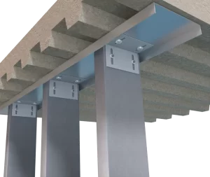
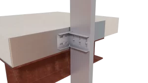
The attachment of DriftClip DSLS to the primary structure may be made with PAFs, screws, or bolt anchors depending on the base material (steel or concrete) and the design configuration. The step bushings used for attachment to structure are designed for use with ¼” maximum diameter fasteners. Designing this connection is the responsibility of the Structural Engineer of Record, and a minimum of two fasteners must be used. A minimum of 3.5″ of DSLS is required for attachment to steel structure and a minimum of 6″ is required for attachment to concrete structure.
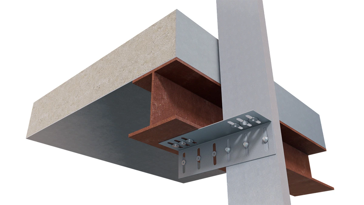
Drift Steel Frame Bypass Connection
Installation Instructions
- Attach DriftClip DSLS to structure with specified fasteners through step bushings.
- Attach to stud with #12 provided screws through step bushings.
This Connector Features Step Bushing Technology!
Step Bushing Technology is transforming the performance of deflection clips. Designed for optimal movement and reliability, Step Bushings eliminate the need for costly, specialized shoulder screws and the tedious adjustments they require. Instead, they deliver friction-free connections that enable smooth, consistent deflection and exceptional performance.
See the Difference
Watch the video for a side-by-side comparison of a clip deflecting with Step Bushings versus a generic clip using specialized screws. Step Bushing Technology is more than an innovation—it’s a game-changer for efficiency, durability, and simplicity on the job site.
Allowable Loads
Table Notes:
- Design loads are for attachment of DriftClip DSLS to stud only.
- Allowable loads have not been increased for wind, seismic, or other factors.
- DriftClip DSLS allows up to 2″ of vertical deflection (1″ up and 1″ down), and 2″ of lateral drift (1″ left and 1″ right) in plane. Deflection requirements greater than 2″ of lateral drift are available.
- #12 screws are provided for each step bushing attachment to studs. Load requirements do not always require the use of a third screw.
- Attachment of structure to be engineered by others. As a design reference for the structure attachment, reference AISI S100 or screw manufacturers published data for allowable loads for screw fasteners of 1/4″-20 size with various plate thicknesses.
- One row of bridging is recommended at a maximum distance of 18″ from DriftClip to resist torsional effects.
- Return lip added for clips longer than 20″.
- For LRFD strengths contact TSN technical services.
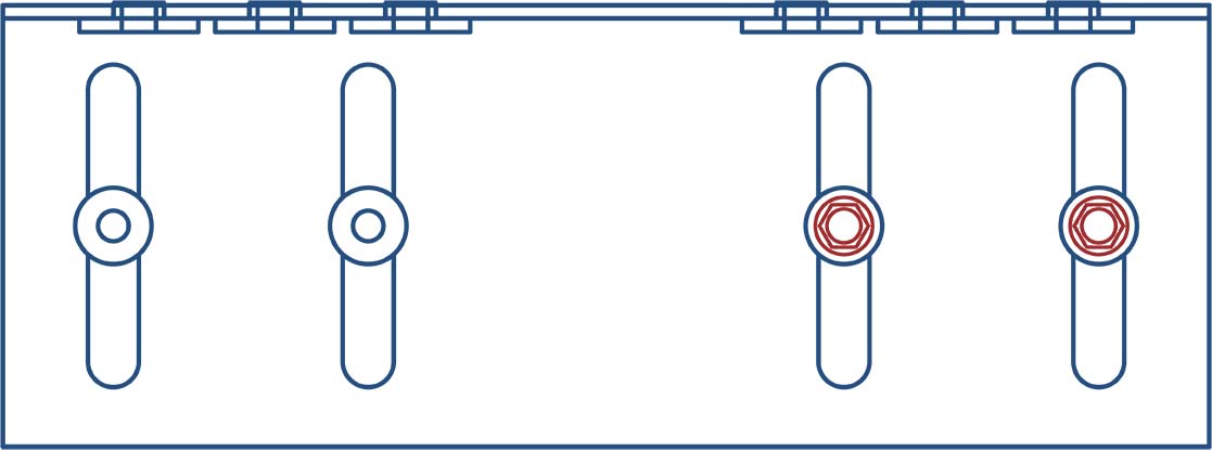 w/2 #12 Screws
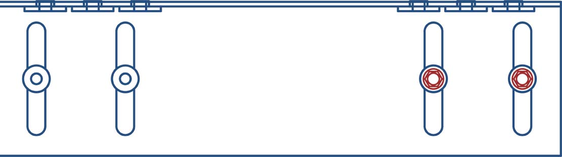 w/2 #12 Screws
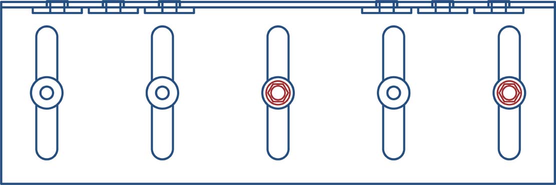 w/2 #12 Screws
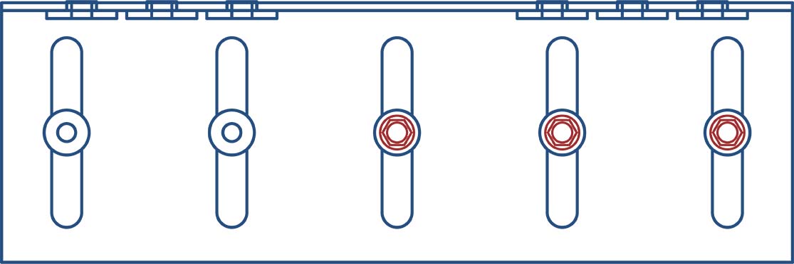 w/3 #12 Screws
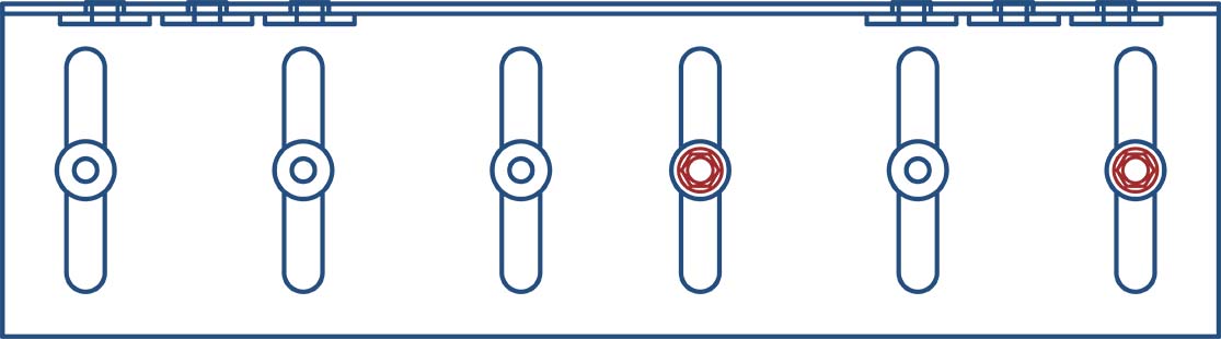 w/2 #12 Screws
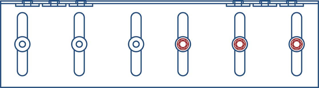 w/3 #12 Screws
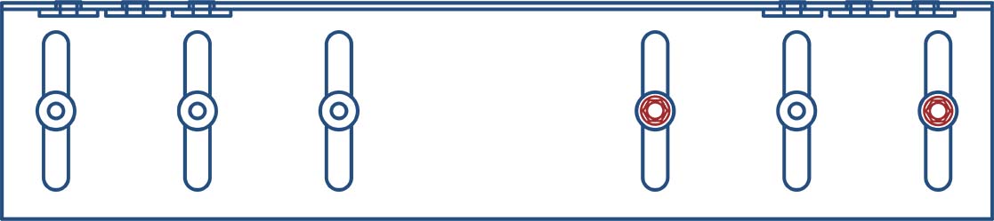 w/2 #12 Screws
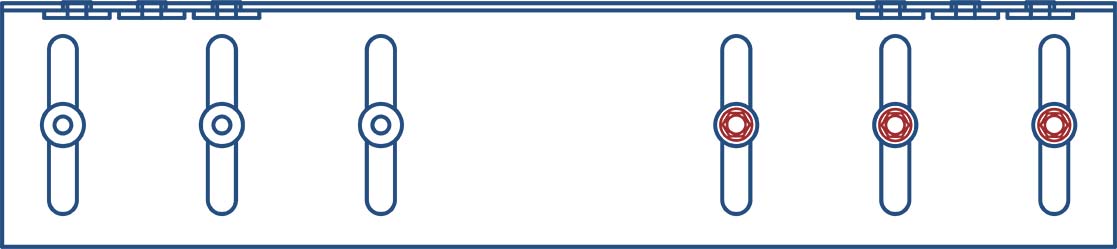 w/3 #12 Screws
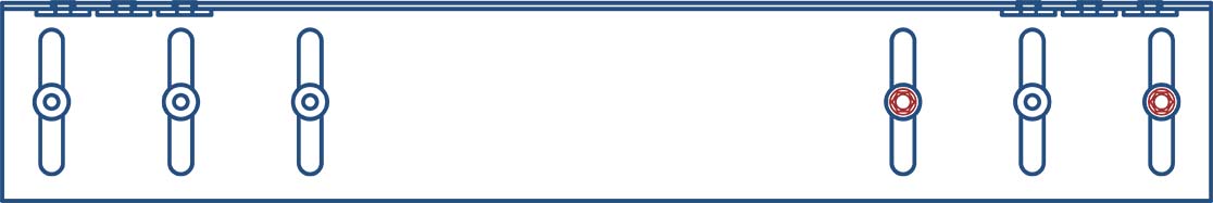 w/2 #12 Screws
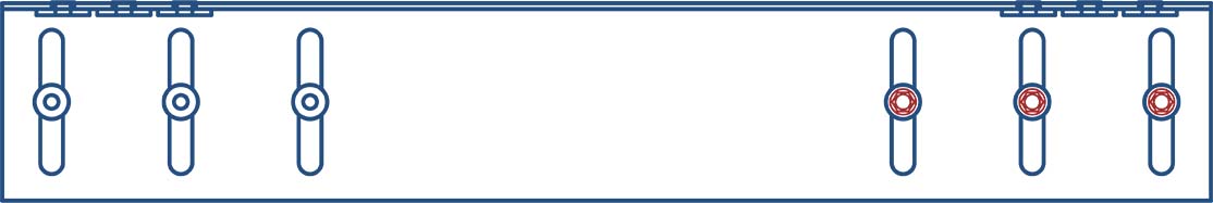 w/3 #12 Screws
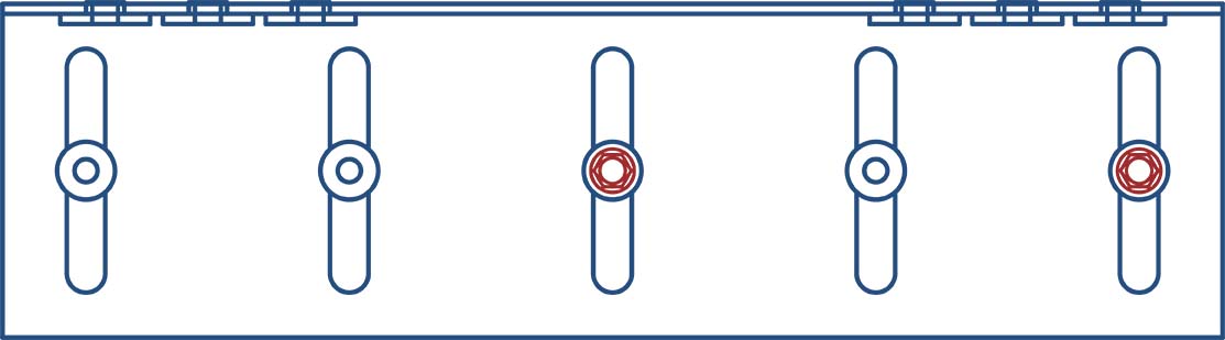 w/2 #12 Screws
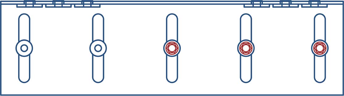 w/3 #12 Screws
 w/2 #12 Screws
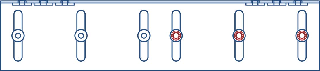 w/3 #12 Screws
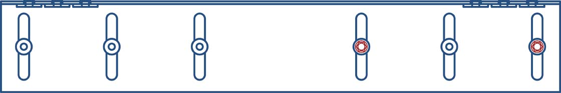 w/2 #12 Screws
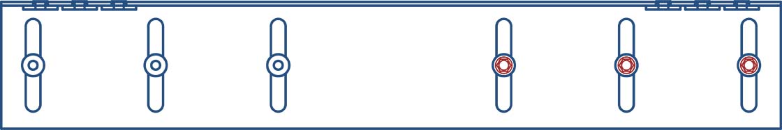 w/3 #12 Screws
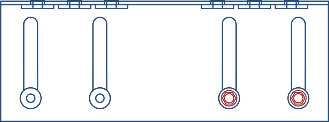 w/2 #12 Screws
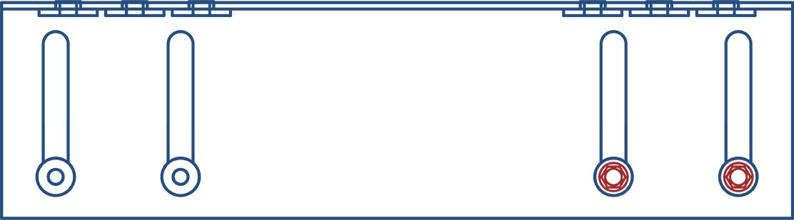 w/2 #12 Screws
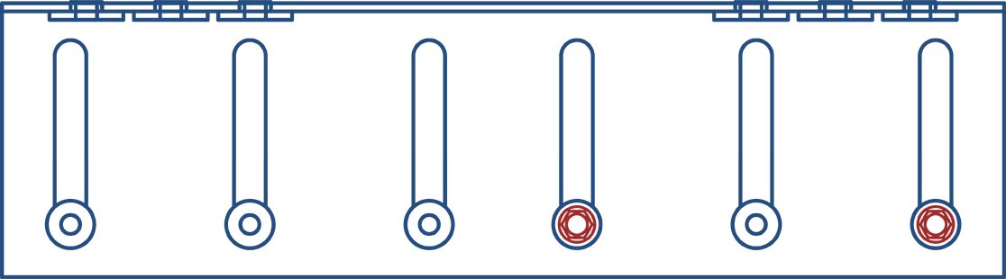 w/2 #12 Screws
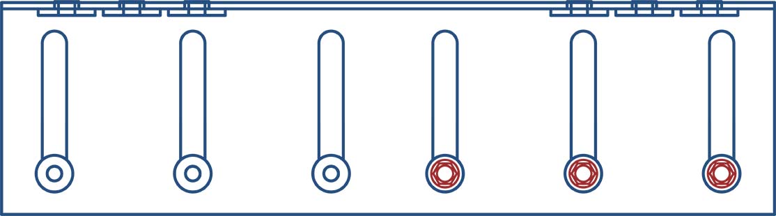 w/3 #12 Screwsw/2 #12 Screwsw/3 #12 Screws
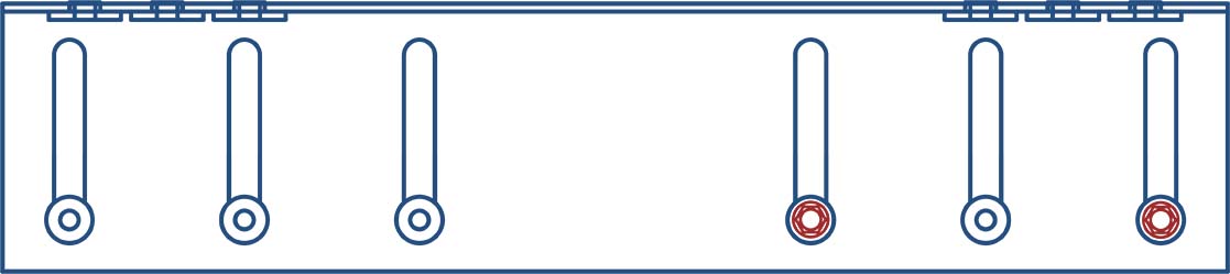 w/2 #12 Screws
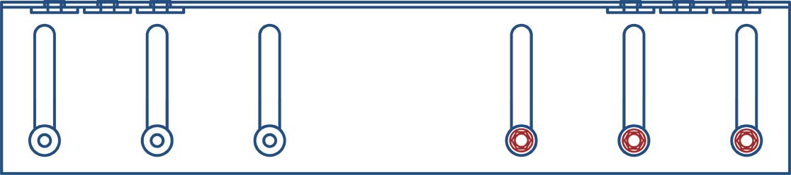 w/3 #12 Screws
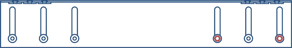 w/2 #12 Screws
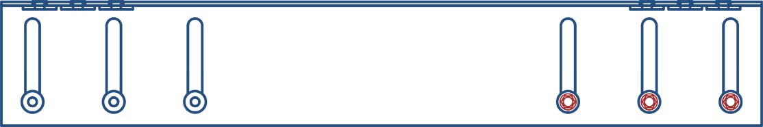 w/3 #12 Screws
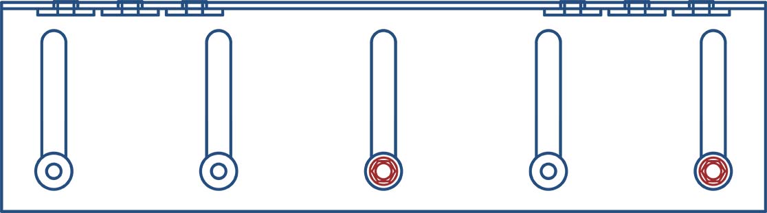 w/2 #12 Screws
 w/3 #12 Screwsw/2 #12 Screws
 w/3 #12 Screws
 w/2 #12 Screws
 w/3 #12 Screws
Load Direction
Fastener Pattern 1
Fastener Pattern 2
More Drift Slide Angle & Track

Follow us on Social Media
