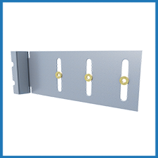
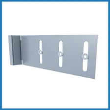
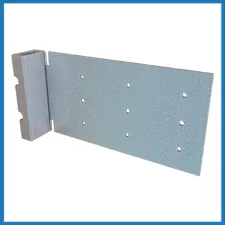
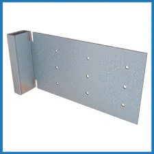
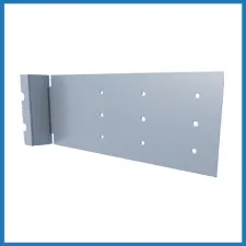
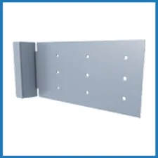
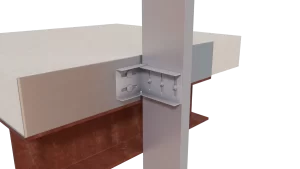
DriftTrak® For Bypass
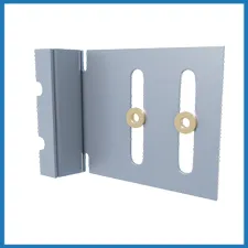
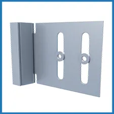
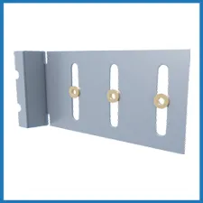
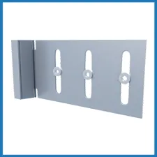
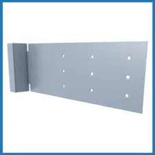
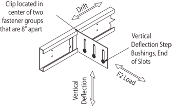
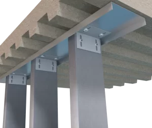
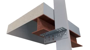
This drift slide track incorporates the DriftTrak member with the DriftTrak DTSLB slide angle or DriftTrak DTLB rigid angle and is used to connect exterior cold-formed steel curtain wall studs to the primary structure while bypassing the slab. Use the DTSLB clip angle for up to 2” vertical deflection (1” up and down) or DTLB clip angle for a rigid connection with no vertical deflection. The DriftTrak provides free lateral drift or the DTSLB/DTLB can be locked into with a locking angle place to prevent lateral movement.
Features
- DTSLB is ICC-ES Approved, report #ESR-2049
- Grooves in 1” leg pass over fastener heads
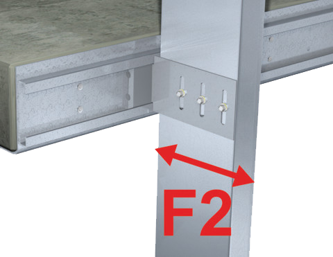
- DTSLB-HD clips without notches for greater F2 outward load capacity.
- Locking Angle DT-LA is available to lock the horizontal movement of the wall panel after installation for cases of no drift requirements.
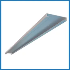
- DriftTrak is available in 12’ lengths.
- Load-rated positive mechanical attachment at each stud
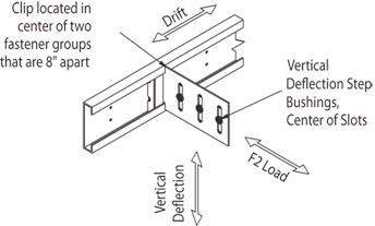
- Patented Step Bushing Technology® provides friction-free motion for smooth vertical deflection
- Eliminates loose friction-held assemblies, heavy deep-leg track, & top row of wall bridging/strapping
- Load-rated #12 screws provided for vertical deflection connection to stud web
- Track DTLB, & DTSLB-HD manufactured with certified, 50ksi, 97mil, G90 cold-formed steel
- DTSLB manufactured with certified, 50ksi, 68mil, G90 cold-formed steel
Material Composition
Track, DTLB, & DTSLB-HD Material: ASTM A1003/A1003M Structural Grade 50 (340) Type H, ST50H (ST340H): 50ksi (340MPa) minimum yield strength, 65ksi (450MPa) minimum tensile strength, 97mil minimum thickness (12 gauge, 0.1017″ design thickness) with ASTM A653/A653M G60 (Z180) hot dipped galvanized coating.
DTSLB Clip Material: ASTM A1003/A1003M Structural Grade 50 (340) Type H, ST50H (ST340H): 50ksi (340MPa) minimum yield strength, 65ksi (450MPa) minimum tensile strength, 68mil minimum thickness (14 gauge, 0.0713″ design thickness) with ASTM A653/A653M G90 (Z275) hot dipped galvanized coating.
Catalogs
TSN’s Product Catalogs are an essential resource for the design of cold formed steel. Developed by Engineers, the catalogs contain design data for members, connectors, and fasteners. DriftTrak® Bypass can be found in the following Catalogs:
|
|
|


For a full list of our product catalogs, specification sections, inspection checklists, and research reports please click here.


Order Information
Nomenclature
The DriftTrack assembly requires the member (DT-12ft) and the connector
(DTSLB/DTLB). DTSLB is classified by multiplying stud depth by 100, followed by “HD,” based on F2 strength required.
Refer to load tables.*
Example:6″ stud depth, with an outward load (F2) of 1,000 lbs
Designate: DT-12ft & DTSLB600-HD
* Clips (DTSLB/DTLB) and track (DT-12ft) are ordered/sold separately.
** Notches are standard in DriftTrak DTSLB. For greater F2 outward load capacity, use DTSLB-HD clips without
notches. Refer to Allowable Load Table.
DriftTrak® Bypass Downloads

DriftTrak® Bypass Applications
The unique design of DriftTrak allows it to be installed to provide any combination of movement allowing or rigid connections in the vertical and horizontal directions. Attachment to the primary structure may be made with a PAF, screw/bolt anchors, or weld and is dependent upon the base material (steel or concrete) and the design configuration.
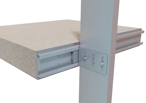
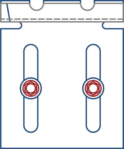
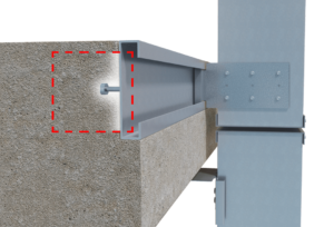
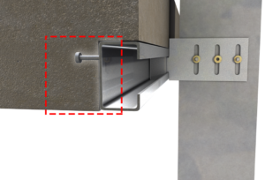
Curtain Wall Slab Bypass as a Drift & Vertical Deflection Connection
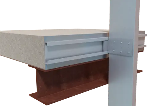
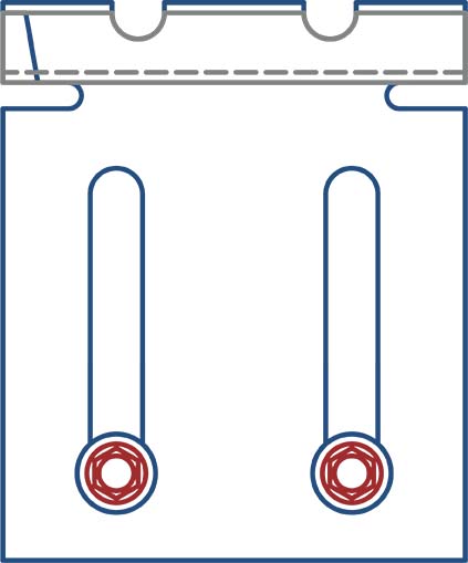
Curtain Wall Slab Bypass as a Drift Connection with No Vertical Deflection
Installation Instructions
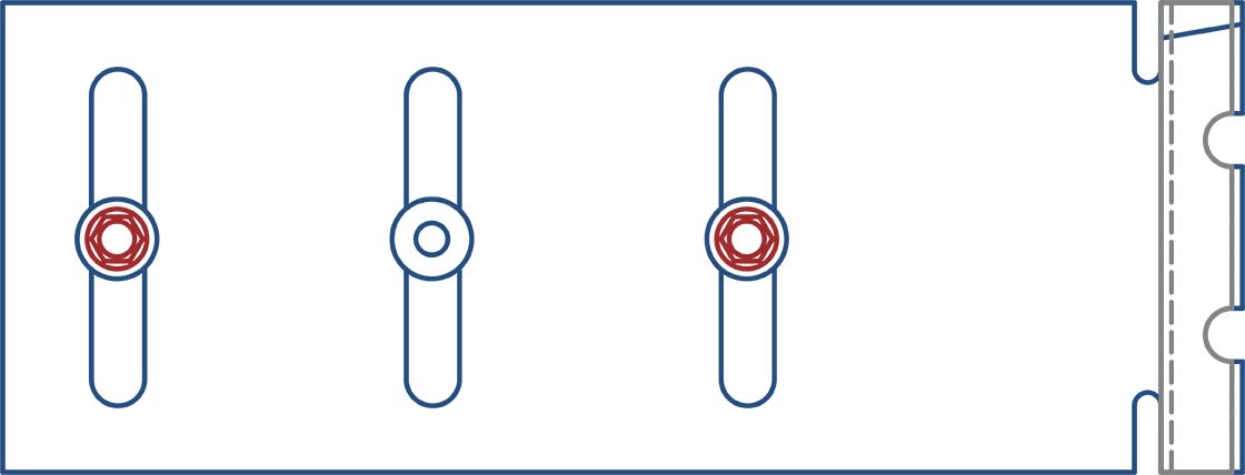
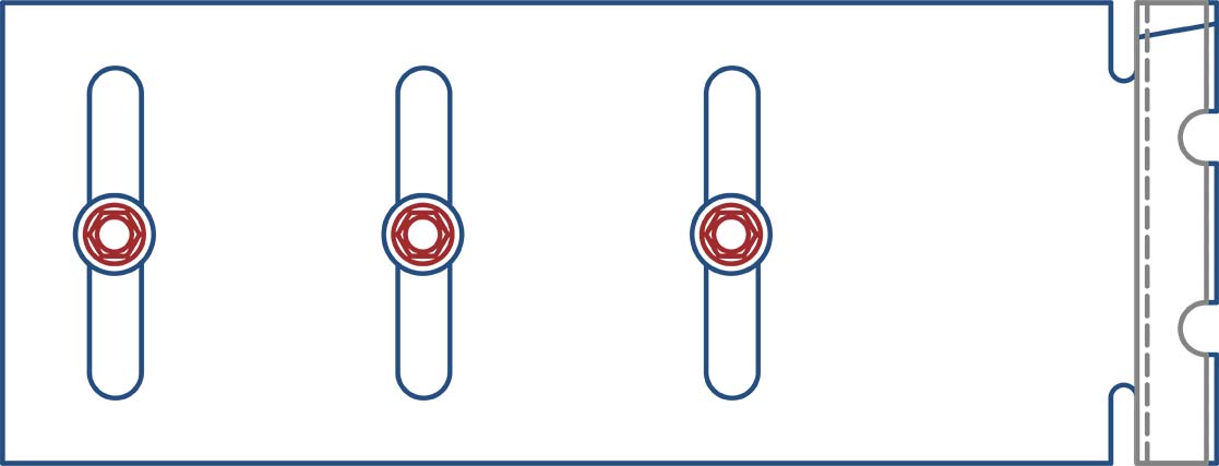
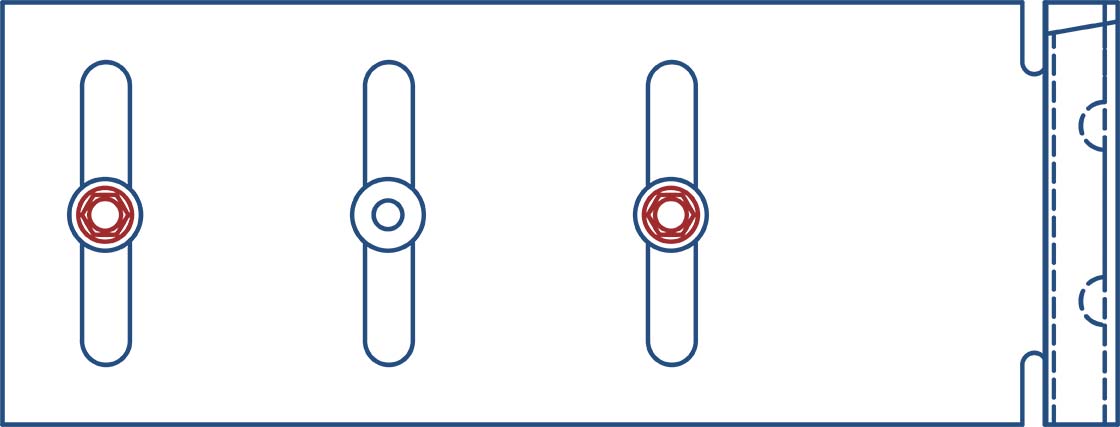
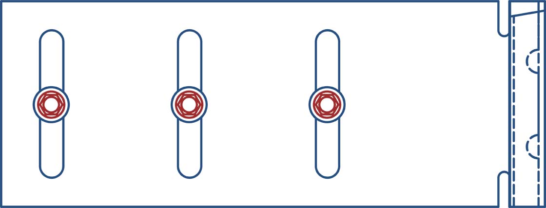
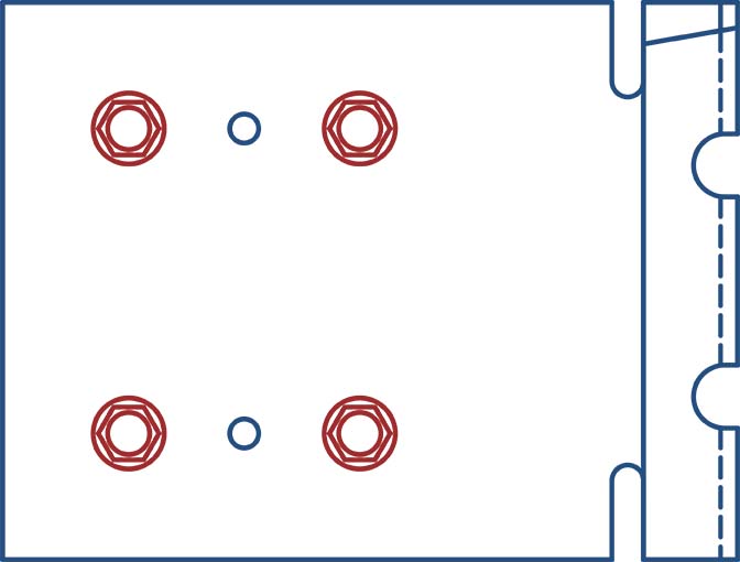
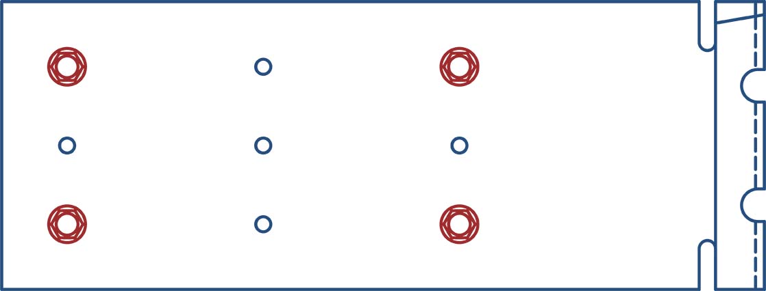
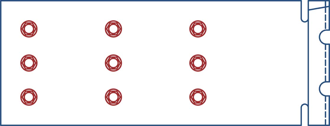
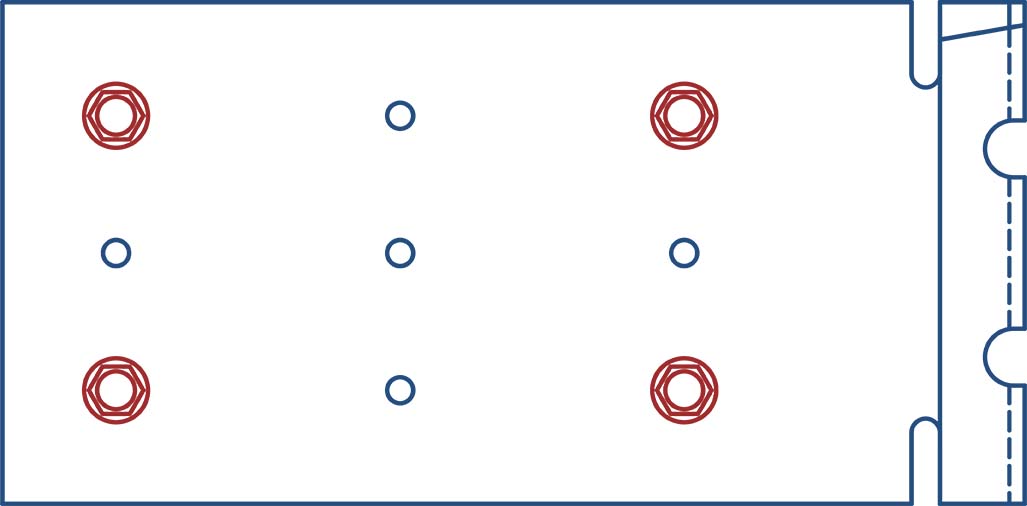
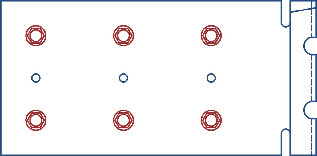
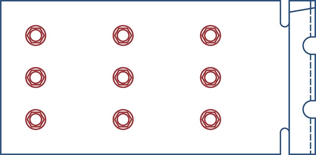
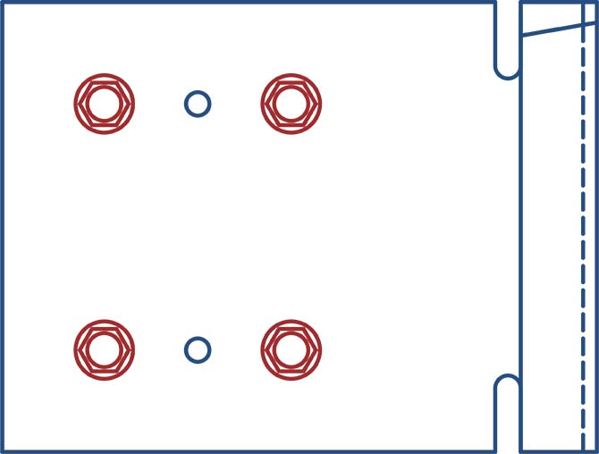
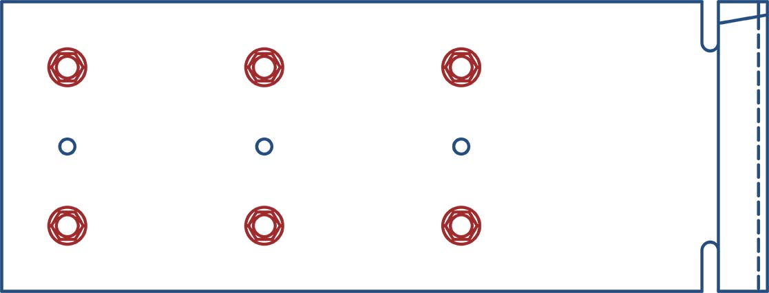
- Fastener Pattern 1 replicates a condition of out-of-plane wind or seismic force with no vertical live load deflection and full in-plane drift.
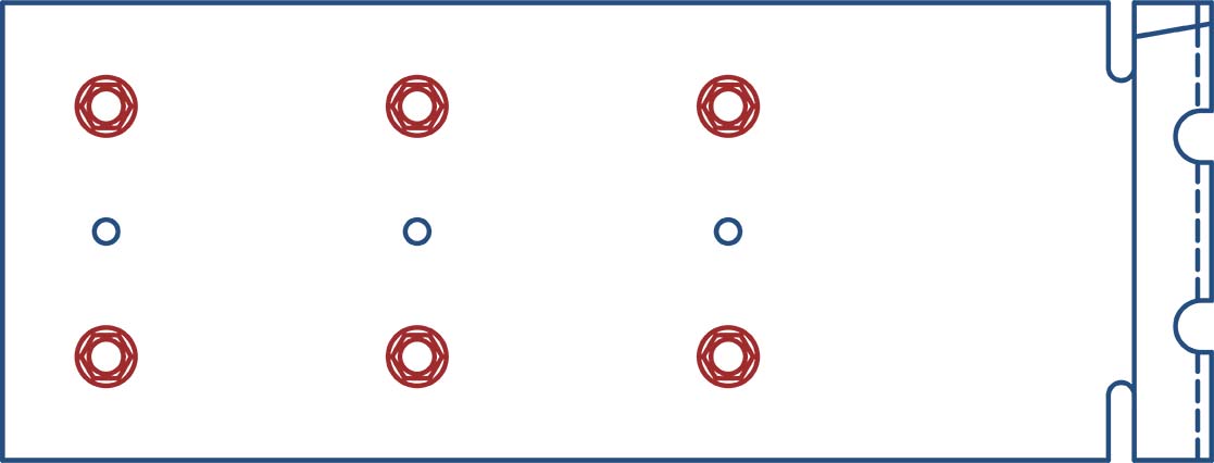
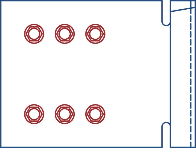
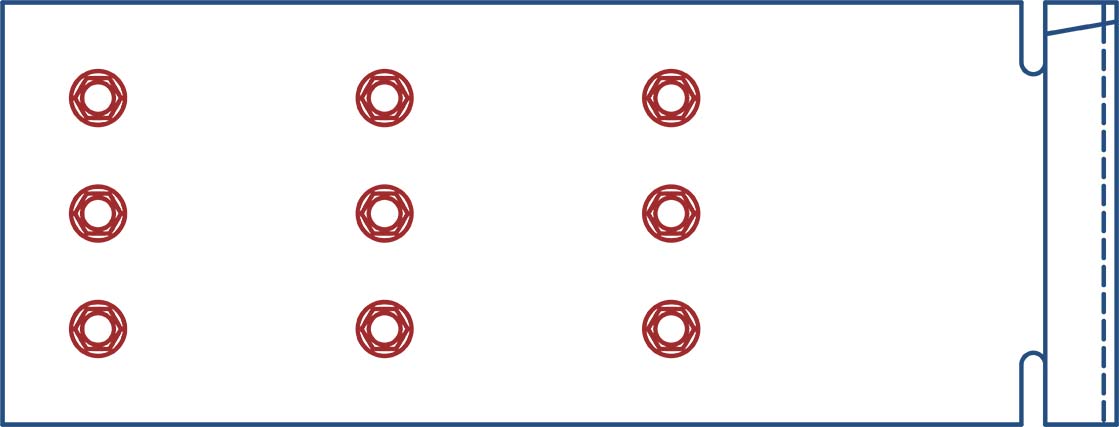
- Fastener Pattern 2 replicates a condition of out-of-plane wind or seismic force with full vertical live load deflection and full in-plane drift.
Notes:
- Allow a minimum of 0.875″ from the structure to the inside flange of the bypassing stud to allow for track attachment.
- One row of bridging is recommended at a maximum distance of 12″ from DriftTrak to resist torsional effects.
- To lock lateral movement, fasten DT-LA (Locking Angle) to DriftTrak components using #12 screws (not included). Locking is recommended at 4 ft. spacing or 3rd stud, max.
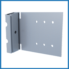
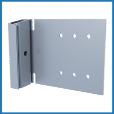
DTLB Installation
DriftTrak® Bypass Allowable Loads
2 Screws
3 Screws
2 Screws
3 Screws
2 Screws
3 Screws
2 Screws
3 Screws
Notes:
- Design loads are for attachment of DriftTrak DT w/ DTSLB to stud only.
- Allowable loads have not been increased for wind, seismic, or other factors.
- Clips are manufactured to fit into DriftTrak DT. DriftTrak DT w/ DTSLB allows up to 2″ of vertical deflection (1″ up and 1″ down), and free lateral movement of the structure.
- #12 screws are provided for each step bushing attachment to studs. Load requirements don’t always justify use of a third screw.
- Attachment to structure at 8″ or 16″ spacing to be engineered by others.
- One row of bridging is recommended at a maximum distance of 18″ from DriftTrak DT w/ DTSLB to resist torsional effects.
- Notches are standard in DTSLB clips. For greater F2 load capacities, use DTSLB-HD clips without notches. Refer to allowable load tables.
- Allow a minimum of 7/8″ from the structure to the inside flange of the bypassing stud to allow for track attachment.
- Total offset of stud from the edge of slab should not exceed 2″ for DriftTrak DT w/ DTSLB362/400 or DTSLB600 clips.
- Total offset of stud from the edge of slab should not exceed 3-1/4″ for DriftTrak DT w/ DTSLB800 clips.
- Total offset is measured from the edge of slab to the inside face of the stud.
- For LRFD strengths contact TSN technical services.
Structure (or Welded on Both Sides)
2 Screws
Structure (or Welded on Both Sides)
2 Screws
Structure (or Welded on Both Sides)
2 Screws
Structure (or Welded on Both Sides)
2 Screws
Notes:
- Design loads are for attachment of DriftTrak DT w/ DTSLB-HD to stud only.
- Allowable loads have not been increased for wind, seismic, or other factors.
- Clips are manufactured to fit into DriftTrak DT. DriftTrak DT w/ DTSLB-HD allows up to 2″ of vertical deflection (1″ up and 1″ down), and free lateral movement of the structure.
- #12 screws are provided for each step bushing attachment to studs. Load requirements don’t always justify use of a third screw.
- Attachment to structure at 8″ or 16″ spacing to be engineered by others.
- One row of bridging is recommended at a maximum distance of 18″ from DriftTrak DT w/ DTSLB-HD to resist torsional effects.
- Allow a minimum of 7/8″ from the structure to the inside flange of the bypassing stud to allow for track attachment.
- Total offset of stud from the edge of slab should not exceed 2″ for DriftTrak DT w/ DTSLB362/400-HD or DTSLB600-HD clips.
- Total offset of stud from the edge of slab should not exceed 3-1/4″ for DriftTrak DT w/ DTSLB800-HD clips.
- Total offset is measured from the edge of slab to the inside face of the stud.
- For LRFD strengths contact TSN technical services.
Load Direction
Screw Pattern 1:
Replicates a condition of out-of-plane wind or seismic force with no vertical live load deflection and full in-plane drift.
Screw Pattern 2:
Allowable Loads (lbs): DriftTrak® DTLB & DTLB-HD: F2 & 3
Max. Offset = 1" for DTLB362/400
4 Screws
Max. Offset = 1" for DTLB362/400

6 Screws
Max. Offset = 1"" for DTLB600
Max. Offset = 1" for DTLB800 w/ 8" Studs
Max. Offset = 3" for DTLB800 w/ 6" Studs
4 Screws
Max. Offset = 1"" for DTLB600
Max. Offset = 1" for DTLB800 w/ 8" Studs
Max. Offset = 3" for DTLB800 w/ 6" Studs
6 Screws
Max. Offset = 1"" for DTLB600
Max. Offset = 1" for DTLB800 w/ 8" Studs
Max. Offset = 3" for DTLB800 w/ 6" Studs
9 Screws
Max. Offset = 1" for DTLB362/400
4 Screws
Max. Offset = 1" for DTLB362/400
6 Screws
Max. Offset = 1" for DTLB600
4 Screws
Max. Offset = 1" for DTLB600
6 Screws
Max. Offset = 1" for DTLB600
9 Screws
Max. Offset = 1" for DTLB800 w/ 8" Studs
Max. Offset = 3" for DTLB800 w/ 6" Studs
4 Screws
Max. Offset = 1" for DTLB800 w/ 8" Studs
Max. Offset = 3" for DTLB800 w/ 6" Studs
6 Screws
Max. Offset = 1" for DTLB800 w/ 8" Studs
Max. Offset = 3" for DTLB800 w/ 6" Studs
9 Screws
Notes:
- Design loads are for attachment of DriftTrak DT w/ DTLB to stud only.
- Allowable loads have not been increased for wind, seismic, or other factors.
- Clips are manufactured to fit into DriftTrak DT. DriftTrak DT w/ DTLB provides a rigid connection to the stud while allowing free lateral movement of the structure.
- Torsional effects are considered on screw group for F3 allowable loads. It is assumed that all of the torsional moment is taken by the connection to the stud.
- Loads listed reflect force in a single direction. When multiple loads act on the connection, it is the responsibility of the designer to check the interaction of forces.
- Attachment to structure at 8″ spacing to be engineered by others.
- One row of bridging is recommended at a maximum distance of 18″ from DriftTrak DT w/ DTLB if no other stud lateral restraint is present.
- Notches are standard in DTLB clips. For greater F2 load capacities, use DTLB-HD clips without notches. Refer to allowable load tables.
- Allow a minimum of 7/8″ from the structure to the inside flange of the bypassing stud to allow for track attachment.
- Maximum total offset of stud from the edge of slab should not exceed 1″ for DriftTrak DT w/ DTLB362/400 or DTLB600 clips.
- Maximum total offset of stud from the edge of slab should not exceed 1″ for DriftTrak DT w/ DTLB800 clips with 8″ studs and 3″ for DriftTrak DT w/ DTLB800 clips with 6″ studs.
- Maximum total offset is measured as track flange plus the gap from the open face of the track to the inside face of the stud.
- For LRFD strengths contact TSN technical services.
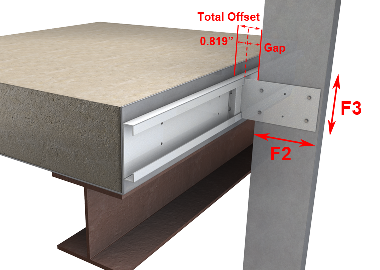
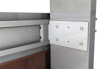
DriftTrak DTLB - Load Direction
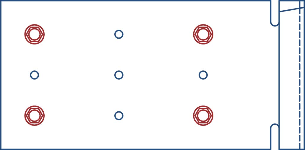
4-Hole Screw Pattern

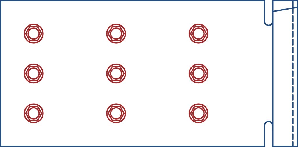
6-Hole Screw Pattern
Allowable Loads (lbs): DriftTrak® DTLB-HD: F2 & 3
Max. Offset = 1" for DTLB362/400-HD
4 Screws
Max. Offset = 1" for DTLB362/400-HD
6 Screws
Max. Offset = 1" for DTLB600-HD
Max. Offset = 1" for DTLB800-HD w/ 8" Studs
Max. Offset = 3" for DTLB800-HD w/ 6" Studs

4 Screws
Max. Offset = 1" for DTLB600-HD
Max. Offset = 1" for DTLB800-HD w/ 8" Studs
Max. Offset = 3" for DTLB800-HD w/ 6" Studs
6 Screws
Max. Offset = 1" for DTLB600-HD
Max. Offset = 1" for DTLB800-HD w/ 8" Studs
Max. Offset = 3" for DTLB800-HD w/ 6" Studs
9 Screws
Max. Offset = 1 for DTLB362/400-HD
4 Screws
Max. Offset = 1 for DTLB362/400-HD
6 Screws
Max. Offset = 1" for DTLB600-HD
4 Screws
Max. Offset = 1" for DTLB600-HD

6 Screws
Max. Offset = 1" for DTLB600-HD
9 Screws
Max. Offset = 1" for DTLB800-HD w/ 8" Studs
Max. Offset = 3" for DTLB800-HD w/ 6" Studs
4 Screws
Max. Offset = 1" for DTLB800-HD w/ 8" Studs
Max. Offset = 3" for DTLB800-HD w/ 6" Studs
6 Screws
Max. Offset = 1" for DTLB800-HD w/ 8" Studs
Max. Offset = 3" for DTLB800-HD w/ 6" Studs
9 Screws
Notes:
- Design loads are for attachment of DriftTrak DT w/ DTLB-HD to stud only.
- Allowable loads have not been increased for wind, seismic, or other factors.
- Clips are manufactured to fit into DriftTrak DT. DriftTrak DT w/ DTLB-HD provides a rigid connection to the stud while allowing free lateral movement of the structure.
- Torsional effects are considered on screw group for F3 allowable loads. It is assumed that all of the torsional moment is taken by the connection to the stud.
- Loads listed reflect force in a single direction. When multiple loads act on the connection, it is the responsibility of the designer to check the interaction of forces.
- Attachment to structure at 8″ spacing to be engineered by others.
- One row of bridging is recommended at a maximum distance of 18″ from DriftTrak DT w/ DTLB-HD if no other stud lateral restraint is present.
- Allow a minimum of 7/8″ from the structure to the inside flange of the bypassing stud to allow for track attachment.
- Maximum total offset of stud from the edge of slab should not exceed 1″ for DriftTrak DT w/ DTLB362/400-HD or DTLB600-HD clips.
- Maximum total offset of stud from the edge of slab should not exceed 1″ for DriftTrak DT w/ DTLB800-HD clips with 8″ studs and 3″ for DriftTrak DT w/ DTLB800-HD clips with 6″ studs.
- Maximum total offset is measured as track flange plus the gap from the open face of the track to the inside face of the stud.
- For LRFD strengths contact TSN technical services.
Related Projects

More Drift Slide Angle & Track


Follow us on Social Media
