DriftTrak® Post-Tensioned Slab
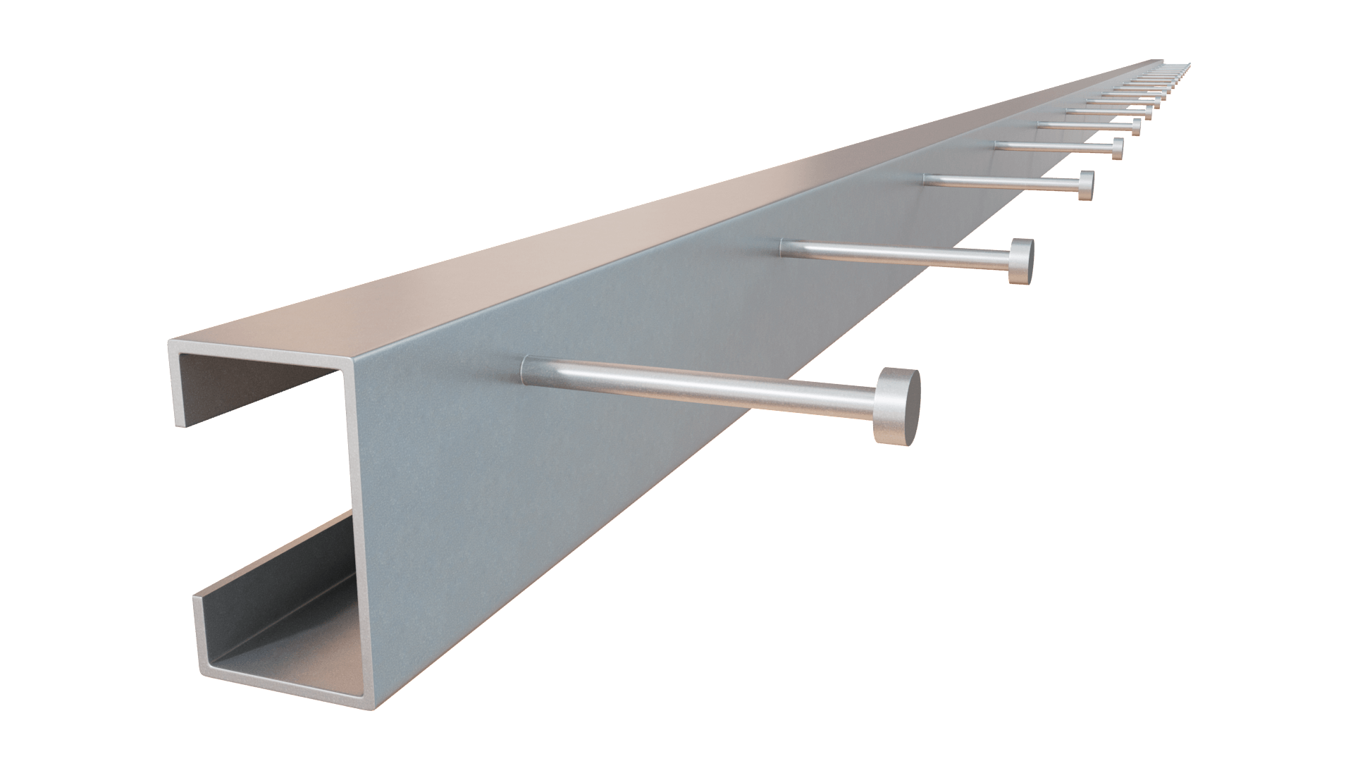
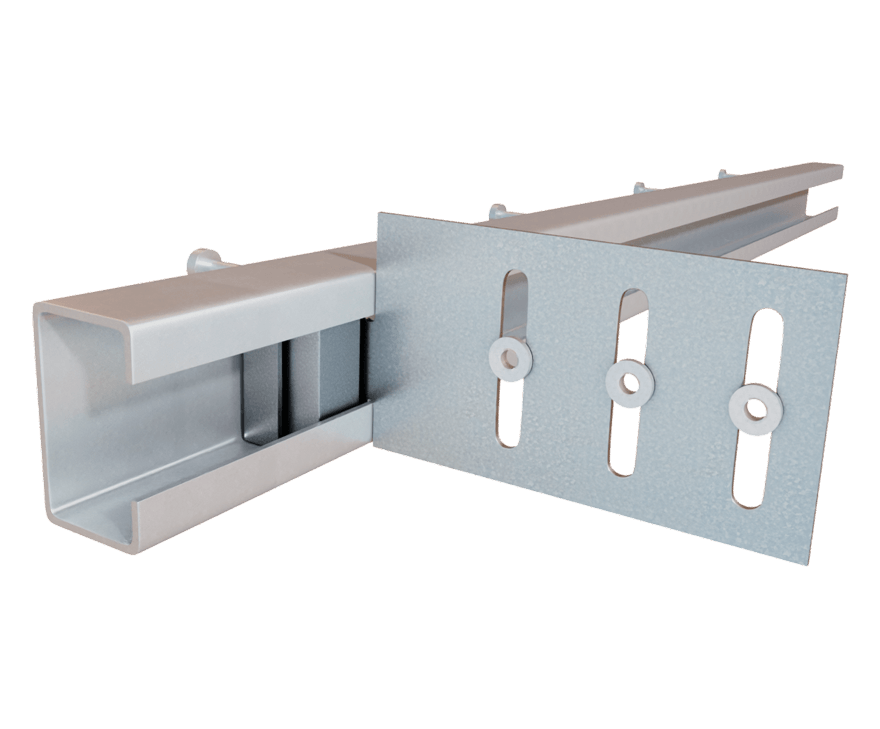
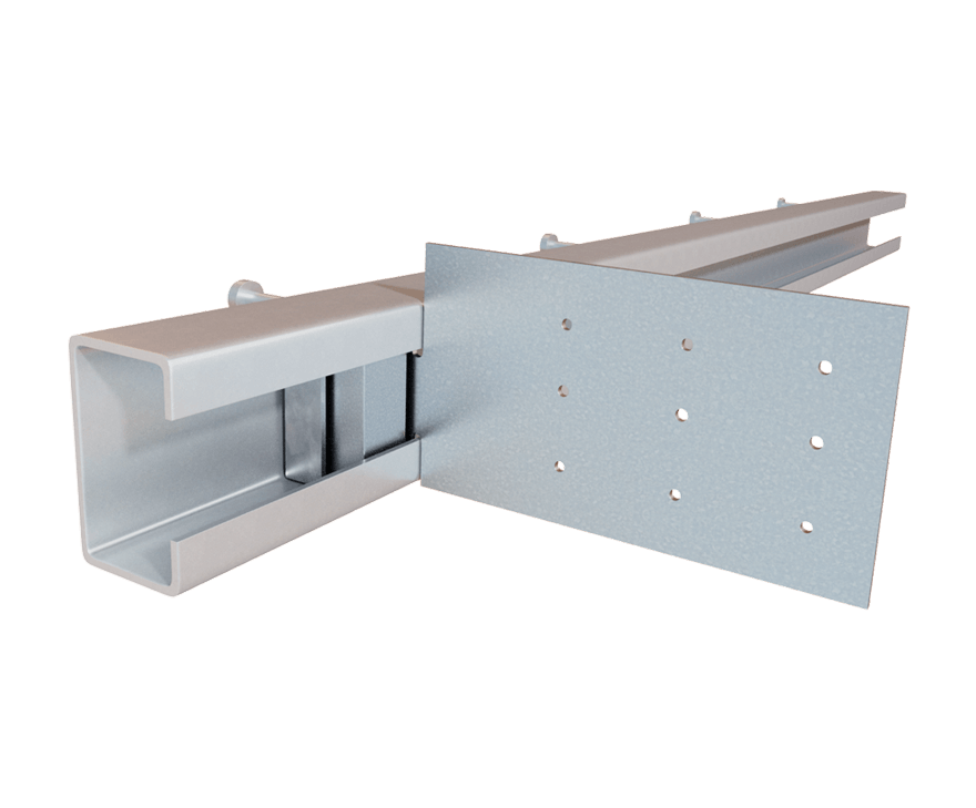
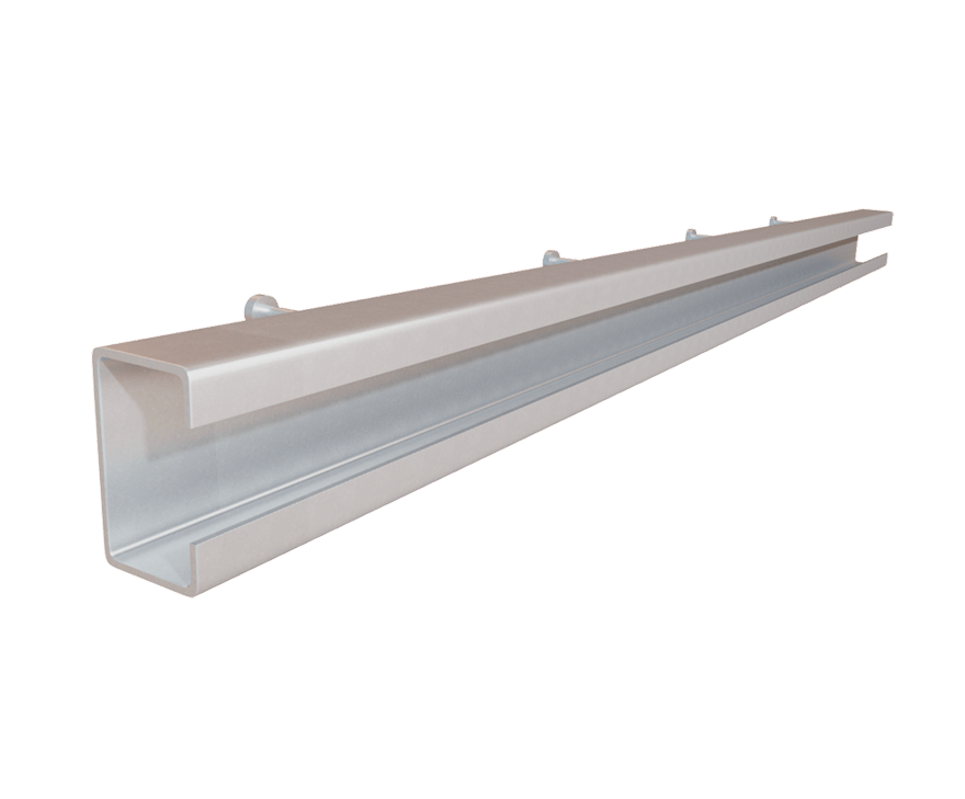
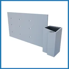
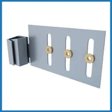
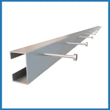
As with DriftTrak Bypass this drift slide track incorporates the studded DriftTrak member with the DriftTrak DTSLB slide angle or DriftTrak DTLB rigid angle to connect exterior cold-formed steel curtain wall studs to the primary structure while bypassing the slab. DriftTrak Post-Tensioned Slab however, can be integrated directly into a post-tensioned slab before pouring, saving the time and expense of installing DriftTrak with lifts after the concrete slab has been poured.
Features
- Locking Angle DT-LA is available to lock the horizontal movement of the wall panel after installation for cases of no drift requirements.
- DriftTrak DTH-PTS is available in 12’ lengths.
- Load-rated positive mechanical attachment at each stud
- Patented Step Bushing Technology® provides friction-free motion for smooth vertical deflection
- Eliminates loose friction-held assemblies, heavy deep-leg track, & top row of wall bridging/strapping
- Load-rated #12 screws provided for vertical deflection connection to stud web
- Track DTLB-PTS, & DTSLB-PTS manufactured with certified, 50ksi, 97mil, G90 cold-formed steel
- DTSLB manufactured with certified, 50ksi, 68mil, G90 cold-formed steel
Material Composition
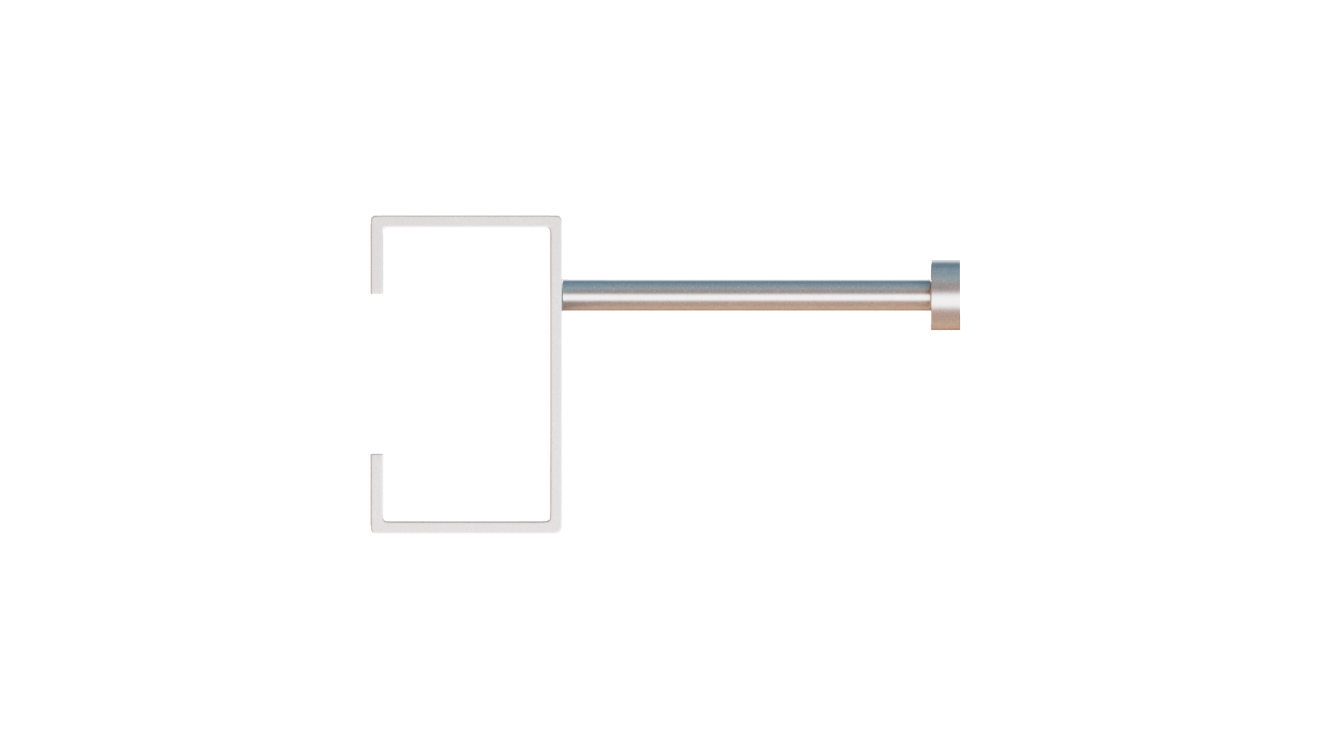
Headed Stud Material: ASTM A29/A108, Grades 1010 through 1020 or equivalent, 45ksi (310MPa) minimum yield strength, 55ksi (380MPa) minimum tensile strength, ⅜” diam. x 3 ⅛” length with ¾” head diameter.
Clip Material: DriftTrak Headed Stud – PTS can be used with DTSLB-PTS and DTLB-PTS clips: ASTM A1003/A1003M Structural Grade 50 (340) Type H, ST50H (ST340H): 50ksi (340MPa) minimum yield strength, 65ksi (450MPa) minimum tensile strength, 97mil minimum thickness (12 gauge, 0.1017” design thickness) with ASTM A653/A653M G90 (Z275) hot dipped galvanized coating.
Catalogs
TSN’s Product Catalogs are an essential resource for the design of cold formed steel. Developed by Engineers, the catalogs contain design data for members, connectors, and fasteners. DriftTrak® PTS can be found in the following Catalogs:
For a full list of our product catalogs, specification sections, inspection checklists, and research reports please click here.
US Patents #7,503,150 & Patent Pending
Order Information
Nomeclature
DriftTrak(R) PTS is manufactured in 10′ or 12′ lengths, with headed studs welded in a single row. The DriftTrak PTS assembly required the member (PTS-10ft or PTS-12ft) and the connector (DTSLB-PTS or DTLB-PTS). DTSLB-PTS or DTLB-PTS is classified by multiplying the stud depth by 100. Refer to load tables.
Example: Vertical Deflection required, left version for installation with 6″ stud
Designate: DriftTrak® PTS w/ DTSLB600-PTS-L
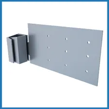
* Clips shown are left versions of DriftTrak DTLB-PTS & DTSLB-PTS. Right side versions are available as standard parts.
** Clips and track sold separately.
*** Standard PTS-10ft includes (8) pre-drilled installation guideholes and Standard PTS-12ft includes (10) pre-drilled installation guideholes
DriftTrak® Post-Tensioned Slab Downloads
DriftTrak® Post-Tensioned Slab Applications
The unique design of DriftTrak Post-Tensioned Slab allows it to be installed prior to pouring the slab. This reduces installation cost as well as safety for installers.
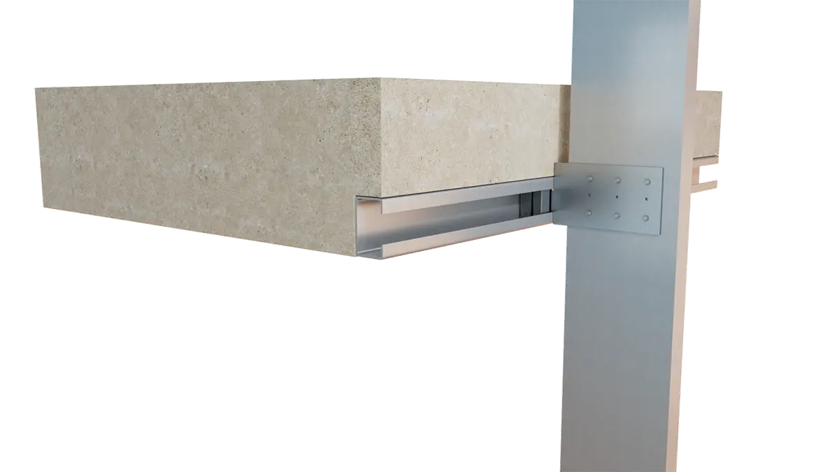
Headed Stud Embedded into a Post-Tensioned Slab for Curtain Wall Slab Bypass as a Drift Connection with No Vertical Deflection
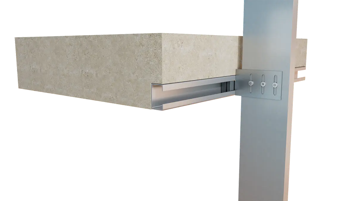
Headed Stud Embedded into Slab for Curtain Wall Slab Bypass as a Drift & Vertical Deflection Connection
Installation Instructions
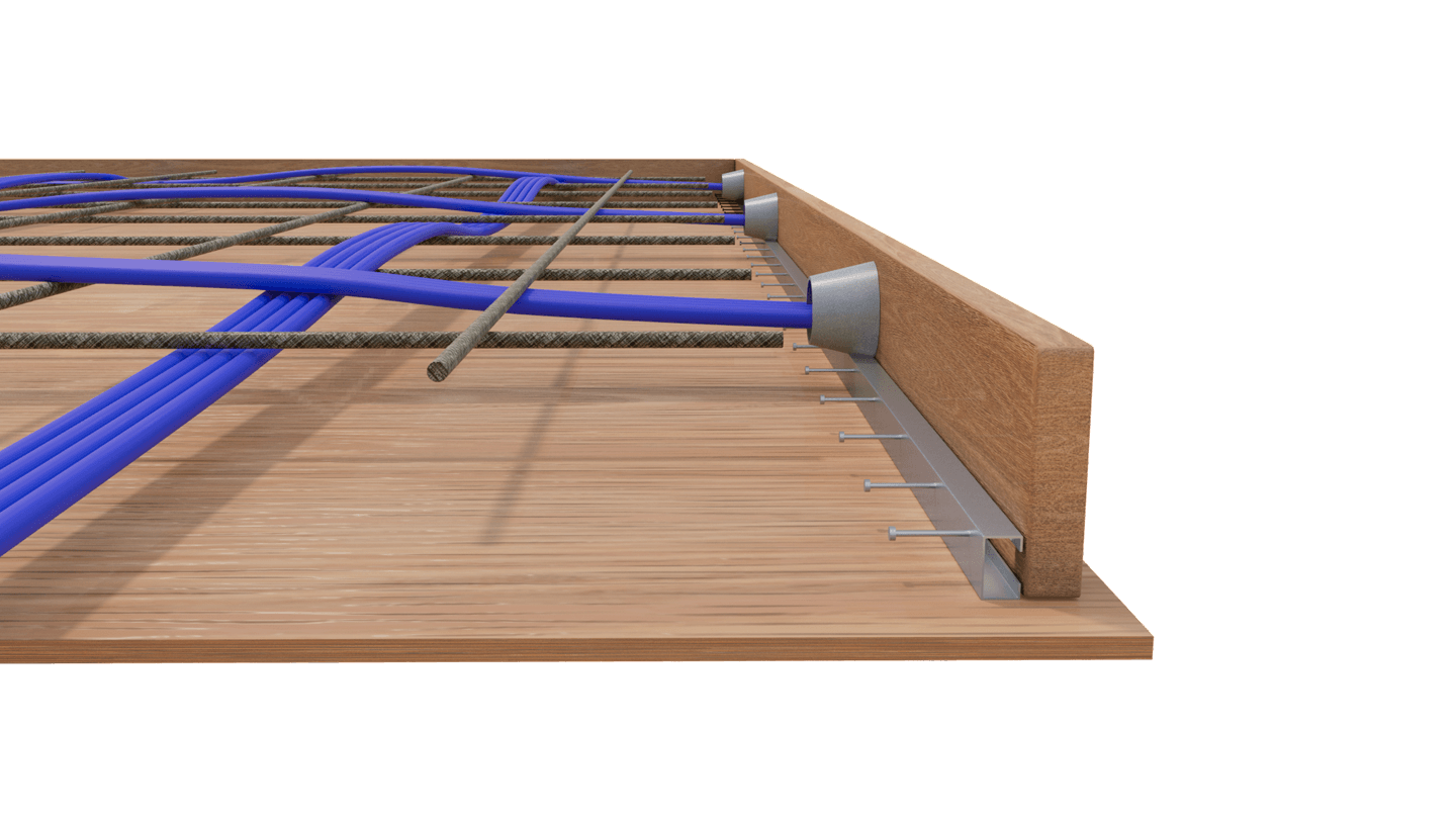
Step 1: Insert DTH-PTS inside concrete slab form prior to pouring concrete.
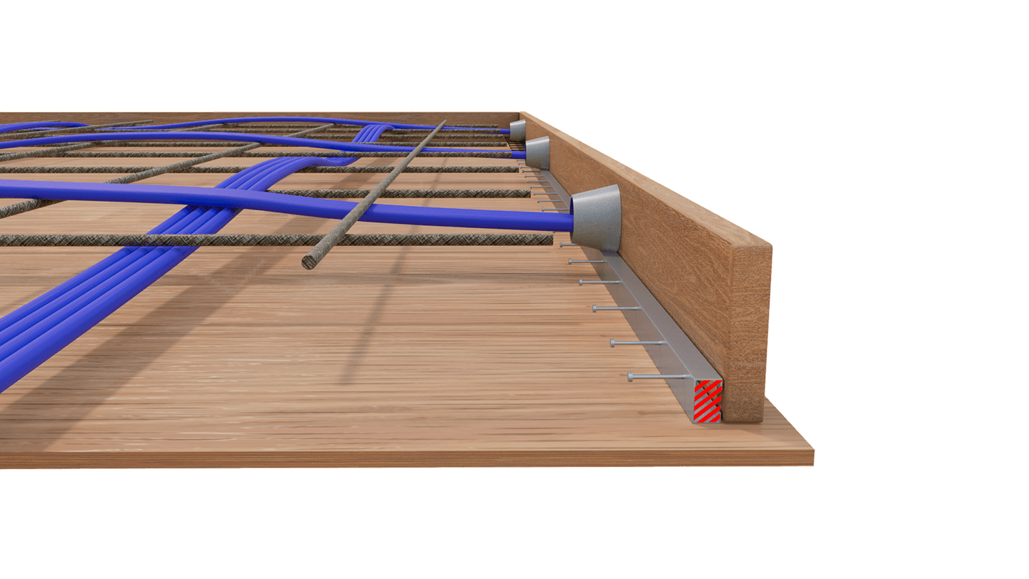
Step 2: Adjust DTH-PTS vertically per design details. Block end to prevent concrete seepage.
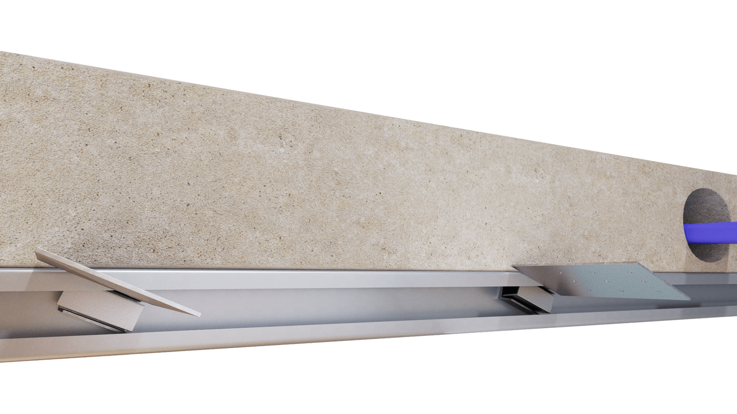
Step 3: After concrete form is removed, twist clips into DTH-PTS track.
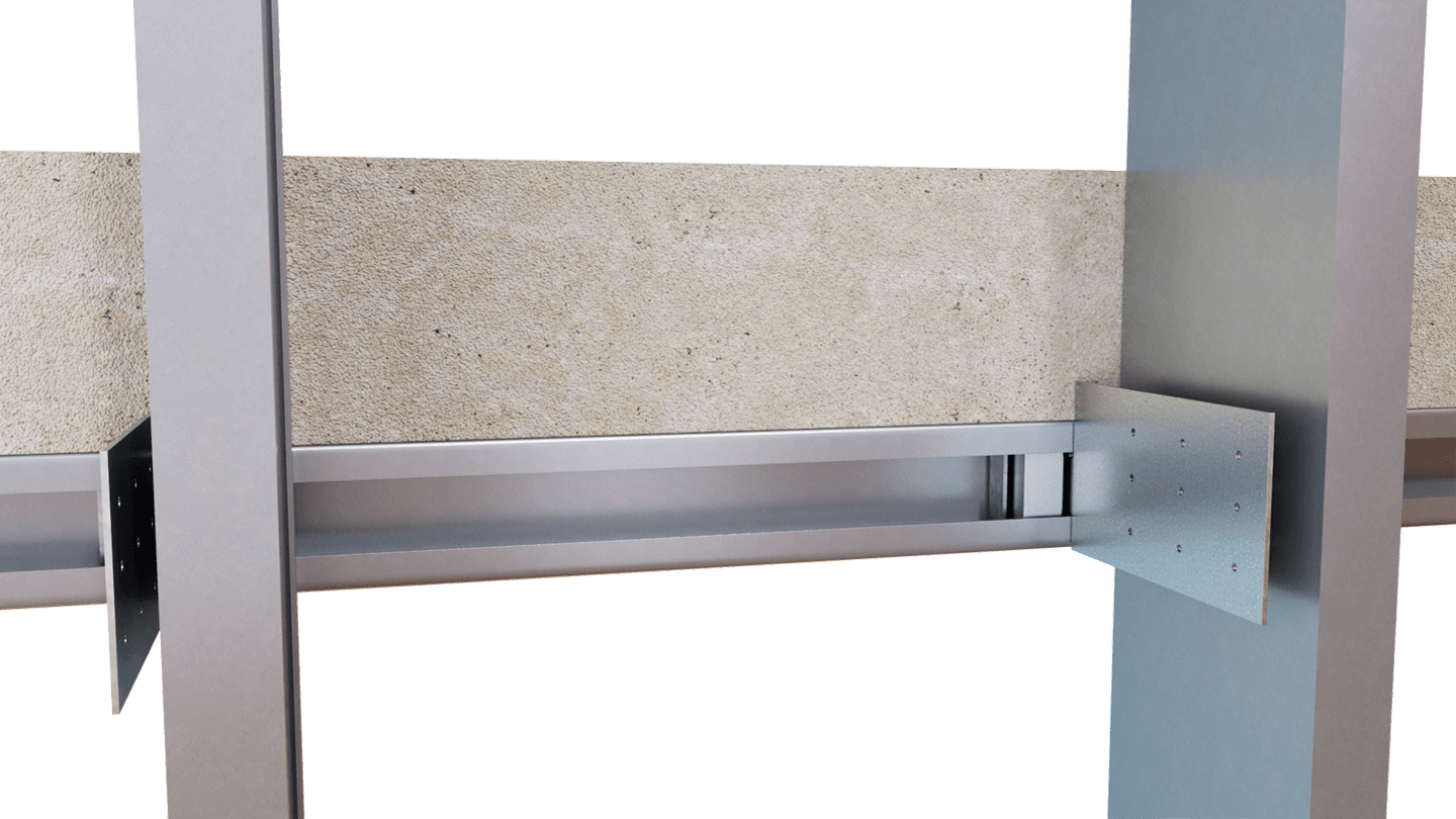
Step 4: Install stud panel and slide clips into place.
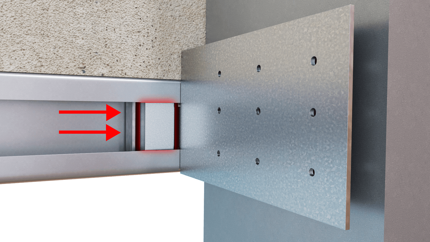
Step 5: Ensure stiffener is in place.
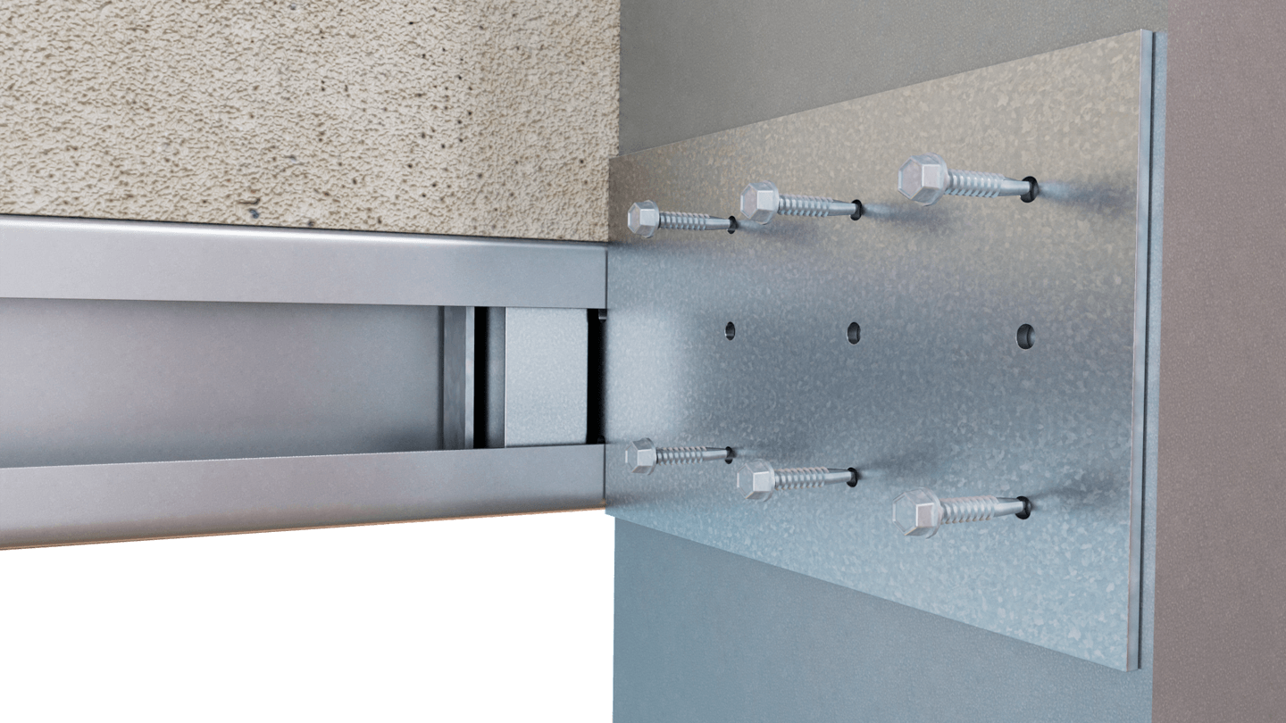
Step 6: Attach stud to clip with specified fasteners through guide holes.
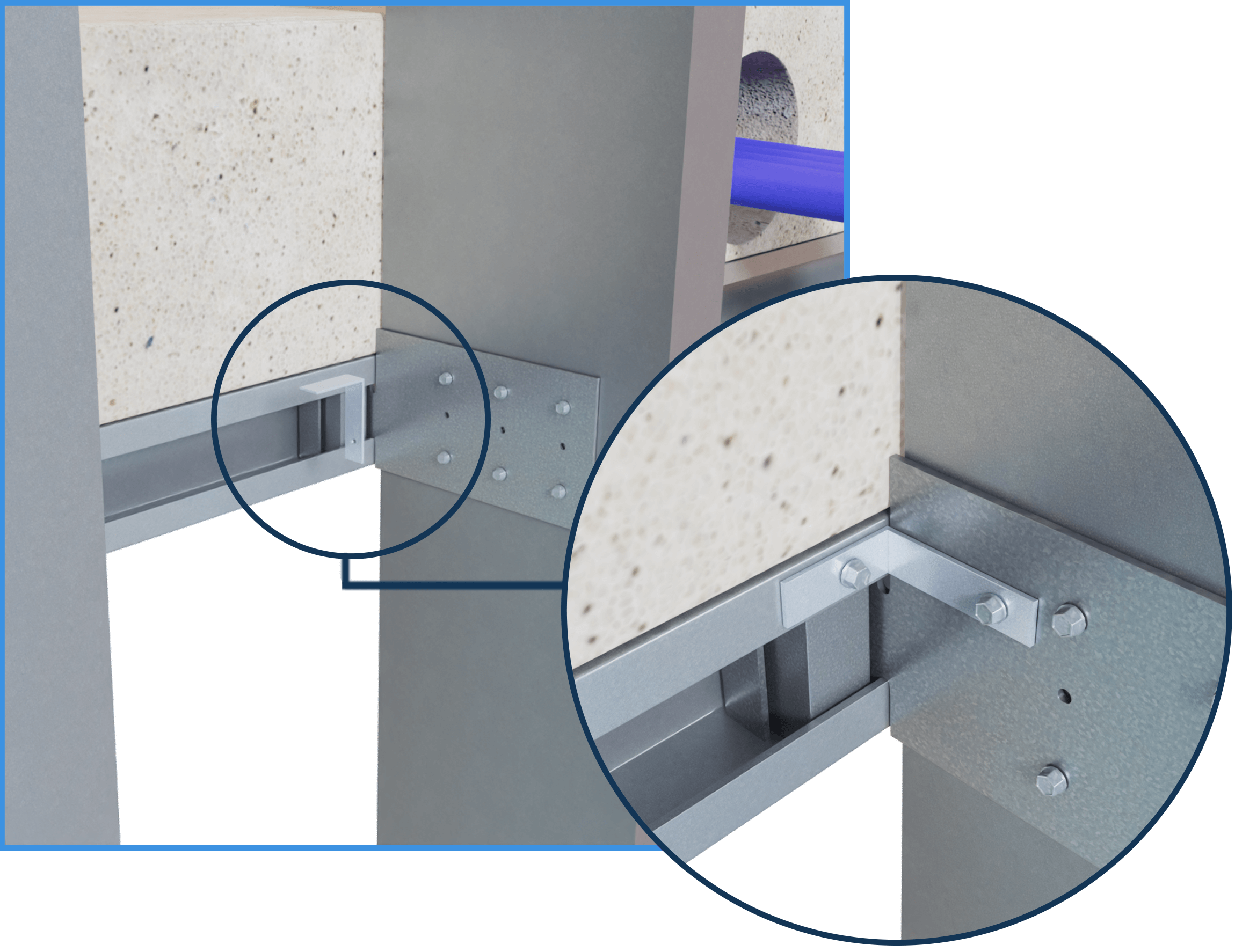
Optional Step: To lock lateral movement, fasten DT-LA (Locking Angle) to DriftTrak components using #12 screws (not included). Locking is recommended at 4 ft. spacing or 3rd stud, max.
DriftTrak® Post-Tensioned Slab Allowable Loads:
Load Table Notes:
- Maximum tension on a single anchor should not exceed 1,600 lbs ASD. In tension and shear, the strength of the anchor itself should be considered. The weld does not need to be considered in tension or shear as the load table and 1,600 lb ASD tension maximum are inclusive of the strength of the welds.
- Designers must check headed stud tension and shear anchorage capacity in concrete per ACI 318 based on actual headed stud edge distance and concrete compressive strength. For more information, call TSN Technical Support at 1-888-474-4TSN.
- Allowable load tables incorporate eccentric loading of fasteners.
- Loads listed reflect force in a single direction. When multiple loads react on the connection, it is the responsibility of the designer to check the interaction of forces.
- Torsional effects are considered on screw group for F3 allowable loads. It is assumed that all of the torsional moment is taken by the connection to the stud.
- Design loads are for attachment of DriftTrak to stud and DriftTrak itself. Load tables reflect horizontal loads (F2) and vertical loads (F3)
- Allowable loads have not been increased for wind, seismic, or other factors.
- Clips are manufactured to fit into the DriftTrak and provide a rigid/slip connection to the stud, and free lateral movement of the structure.
- One row of bridging is recommended at a maximum distance of 18” from DriftTrak if no other stud lateral restraint is present.
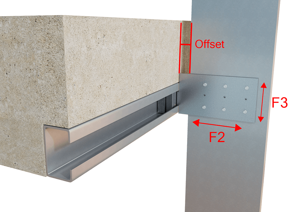
Load Directions
F2 Load Tables

4 Screws

6 Screws

9 Screws

4 Screws

6 Screws

9 Screws

4 Screws

6 Screws

9 Screws

4 Screws

6 Screws

9 Screws
Max. Offset = 1-7/8" for DTSLB600-PTS
Max. Offset = 2-1/2" for DTSLB800-PTS

2 Screws
Max. Offset = 1-7/8" for DTSLB600-PTS
Max. Offset = 2-1/2" for DTSLB800-PTS

3 Screws
Max. Offset = 1-7/8" for DTSLB600-PTS
Max. Offset = 2-1/2" for DTSLB800-PTS

2 Screws
Max. Offset = 1-7/8" for DTSLB600-PTS
Max. Offset = 2-1/2" for DTSLB800-PTS

3 Screws
Load Table Notes:
- Design loads are for attachment of DriftTrak PTS w/ DTSLB-PTS to stud and stud weld to track only.
- Allowable loads have not been increased for wind, seismic, or other factors.
- Clips are manufactured to fit into DriftTrak PTS. DriftTrak PTS w/ DTSLB-PTS allows up to 2″ of vertical deflection (1″ up and 1″ down), and free lateral movement of the structure.
- #12 screws are provided for each step bushing attachment to studs. Load requirements don’t always justify use of a third screw.
- Maximum tension on a single anchor should not exceed 1,600 lbs ASD. In tension, the strength of the anchor itself should be considered. The weld does not need to be considered in tension as the load table and 1,600 lbs ASD maximum tension value are inclusive of the strength of the welds.
- Designers must check headed stud tension anchorage capacity into concrete per ACI 318 based on the actual headed stud edge distance an concrete compressive strength. For more information, call TSN Technical Suppot.
- One row of bridging is recommended at a maximum distance of 18″ from DriftTrak PTS w/ DTSLB-PTS to resist torsional effects.
- Standard offset of stud from the open face of the track should not exceed 1-7/8″ for DriftTrak PTS w/ DTSLB600-PTS clips.
- Standard offset of stud from the open face of the track should not exceed 2-1/2″ for DriftTrak PTS w/ DTSLB800-PTS clips.
- Offset is measured from the open face of the track to the inside face of the stud.
- For LRFD strengths contact TSN technical services.
F3 Load Tables
Load Table Notes:
- Design loads are for attachment of DriftTrak PTS w/ DTLB-PTS to stud and stud weld to track only.
- Allowable loads have not been increased for wind, seismic, or other factors.
- Clips are manufactured to fit into DriftTrak PTS. DriftTrak PTS w/ DTLB-PTS provides a rigid connection to the stud while allowing free lateral movement of the structure.
- Torsional effects are considered on screw group for F3 allowable loads. It is assumed that all of the torsional moment is taken by the connection to the stud.
- Loads listed reflect force in a single direction. When multiple loads act on the connection, it is the responsibility of the designer to check the interaction of forces.
- Maximum tension on a single anchor should not exceed 1,600 lbs ASD. In tension, the strength of the anchor itself should be considered. The weld does not need to be considered in tension as the load table and 1,600 lbs ASD maximum tension value are inclusive of the strength of the welds.
- Designers must check headed stud tension anchorage capacity into concrete per ACI 318 based on the actual headed stud edge distance an concrete compressive strength. For more information, call TSN Technical Suppot.
- One row of bridging is recommended at a maximum distance of 18″ from DriftTrak PTS w/ DTLB-PTS if no other stud lateral restraint is present.
- Standard offset of stud from the open face of the track should not exceed 1-7/8″ for DriftTrak PTS w/ DTLB600-PTS clips.
- Standard offset of stud from the open face of the track should not exceed 2-1/2″ for DriftTrak PTS w/ DTLB800-PTS clips.
- Offset is measured from the open face of the track to the inside face of the stud.
- For LRFD strengths contact TSN technical services.
Follow us on Social Media

